2 - E - 4
READ SECTION
4. Removing and Re-installing the Exposure Unit
Caution: Be sure that the power cord has been unplugged
from the power outlet.
Caution:
1. Use a optics positioning jig when installing the expo-
sure unit.
2. Be sure to perform image adjustment after installing
the exposure unit. (For details, refer to "Adjustment
section".)
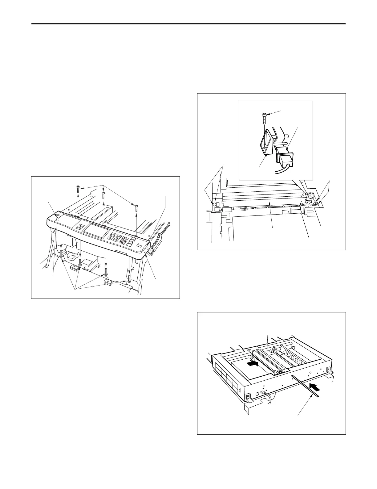
a. Removal procedure
(1) Remove the glass holder plate, original stopper plate,
platen glass and upper cover (center).
(2) Remove the seven set screws, then remove the opera-
tion panel and disconnect three connectors (CN219,
223 and 383).
Set screws
Operation
panel
Set screws
Connector
(CN383)
Connector
(CN223)
Connector
(CN219)
(3) Move the exposure unit to the notch in the main body
frame on the paper exit side.
(4) Remove the set screw, then remove the wiring fixing
plate and disconnect the connector (CN384).
(5) Remove the four set screws, then remove the expo-
sure unit.
b. Re-installation procedure
(1) Insert the Optics positioning jig into the exposure unit
mounting position from the front.
(2) Slide the exposure unit to the paper feed side until it
touches the Optics positioning jig.
(3) Install the exposure unit on the optics wire using the
four set screws.
Exposure unit
Optics positioning jig
Wiring fixing
plate
Exposure unit
Set screws
Set screws
Connector
(CN384)
Set screw