2 - E - 5
READ SECTION
5. Installing the optics wire
Caution:
1. When winding the wire around the pulley, be sure to
run the wire tightly to ensure that it does not ride up the
side of the pulley.
2. When re-tensioning or replacing the optics wire, be
sure to use the optics positioning jig.
3. Be sure to perform image adjustment after replacing or
re-installing the wire. (For details, refer to "Adjustment
section".)
a. Procedure
(1) Remove the exposure unit.
(2) Remove the glass stopper plate.
(3) Remove the six set screws, then remove the front door.
(4) Disconnect the two connectors (CN381 and 388).
(5) Remove the five set screws, then remove the front
cover/lower.
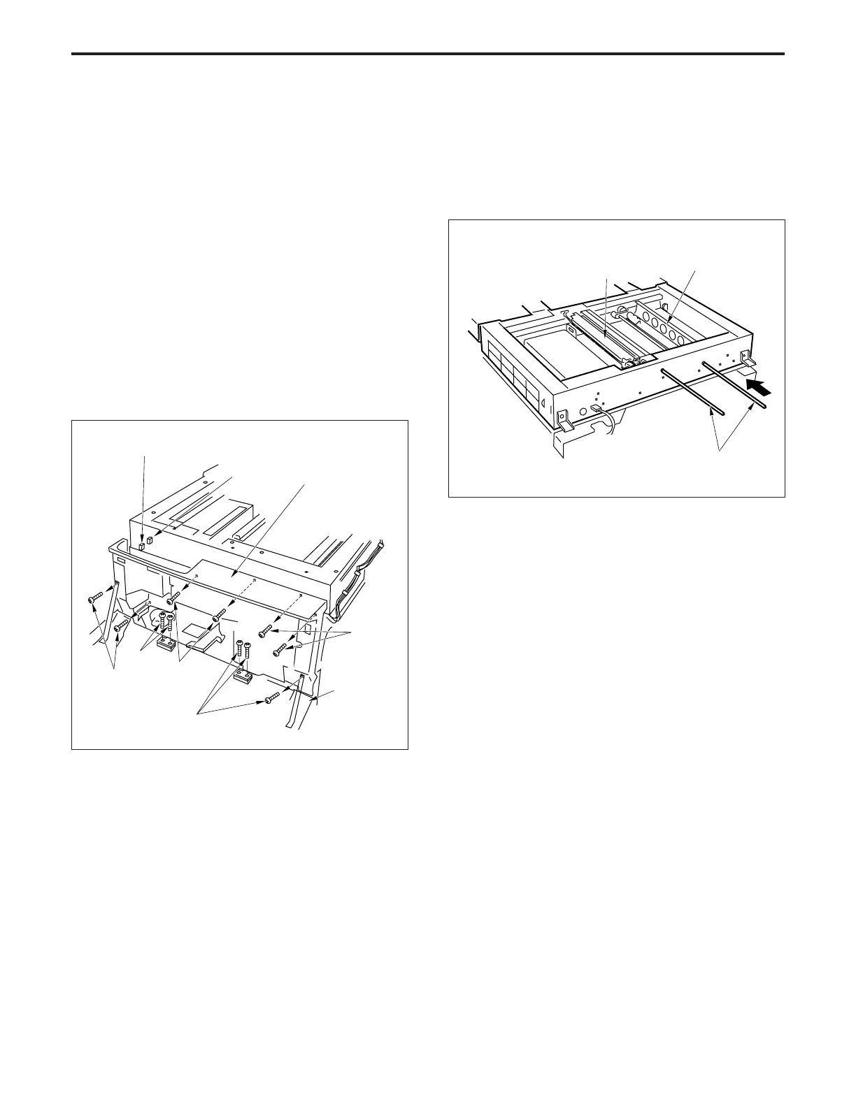
(6) Move the V mirror unit to the paper feed side, then
insert the Optics positioning jigs from the front so as to
fix the V mirror unit. Ensure that the jigs pass through
the V mirror unit.
(7) Insert the Optics positioning jigs to the exposure unit
mounting position from the front.
Connector
(CN388)
Connector
(CN381)
Front door
Set screws
Set
screws
Set screws
Set screws
Set screws
Exposure unit
V mirror unit
Optics
positioning jigs
Front cover/lower