Moog Animatics SmartMotor™ Developer's Guide,Rev. L
Page 220 of 909
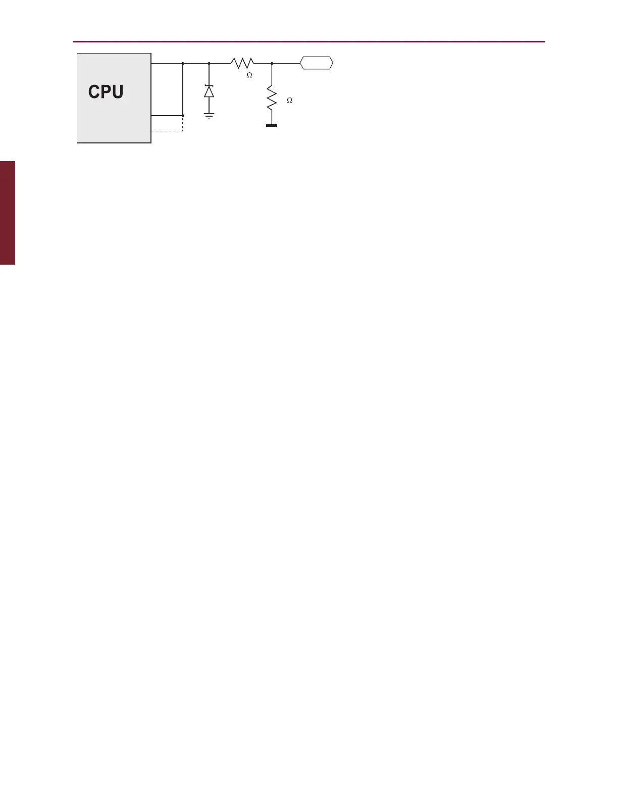
Digital I/O
Analog Input
Counter or Comm
+5V
5k
I/O Pin
5.6V
100
Knowing the SmartMotor's internal
schematic can be useful when design-
ing external interfaces. SmartMotor
I/O is logic 0 for voltages below 1.2V
and logic 1 for voltages above 3.0V.
Note that logic states for voltages
between these are unpredictable.
NOTE: For the D-style SmartMotor, this schematic diagram applies to ports 0–3
and 6; ports 4 and 5 do not use the 100 ohm resistor.
Input impedance for these Class 5 D-style ports is 5 kohms. Input impedance for
Class 5 M-style and Class 6 M-style is 10 kohms. Refer to the corresponding
Connector Pinout table in the SmartMotor Installation & Startup Guide for your
motor.
All SmartMotor I/O points default to inputs when power is applied to the SmartMotor, until the
user program makes a change. Because of the pull-up resistor, the voltage read at each port
will be about 5 VDC. When used as outputs to turn on external devices, it is highly
recommended to design the system so that +5V is OFF and 0V is ON. This will prevent
external equipment from being turned on immediately after power-up, and before the user
program has a chance to take control.
Discrete Input and Output Commands
This section describes the discrete input and output commands available for the SmartMotor.
NOTE: For the 5V I/O in the Class 5 motor's D-Sub connector, the value can be 0 -
6 for I/Os 0 - 6. For the 24V I/O, the value can be 16 - 25 for the ten I/Os 16 - 25.
Discrete Input Commands
x=IN(IO) Gets the state of an I/O bit & puts it in a variable.
x=IN(W,word) Gets the state of an I/O word & puts it in a variable.
x=IN(W,word[,mask]) Gets the state of an I/O word after applying a mask.
Discrete Output Commands
OS(IO) Set a single output to logic 1 or ON.
OS(W,word[,mask]) Set multiple outputs at once, applying a bit mask first.
OR(IO) Reset a single output to logic 0 or OFF.
OR(W,word[,mask]) Reset multiple outputs at once, applying a bit mask first.
OUT(IO)=formula If the bit in formula to the right of the "=" is odd, then set
I/O ON; when even or zero, turn it OFF.
OUT(W,word)=formula Set the I/O group to a value to the right of the "=".
OUT(W,word[,mask])
=formula
Set the I/O group with mask.
For more details, see Part 2: SmartMotor Command Reference on page 238.
Part 1: Programming: Discrete Input and Output Commands