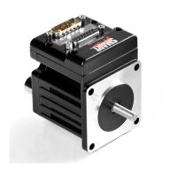
Moog Animatics SmartMotor™ Developer's Guide,Rev. L
Page 227 of 909
Class 5 M-Style Motors: Special Functions of I/O Ports
The on-board I/O ports provide the following special functions:
COM Port pins 4, 5, 6, and 8 A-quad-B or Step-and-Direction counting modes
Ports 2 and 3 Travel limit inputs, brake output
Port 5 Capture input, brake output
Port 6 Go function, brake output
Drive enable input Dedicated input to enable drive
No fault output Dedicated output to indicate when no faults are
preventing motion
NOTE: The brake output function can be pointed to any one of the on-board I/O or
expanded I/O ports.
COM Port Pins 4, 5, 6, and 8 – A-quad-B or Step-and-Direction Modes
These pins are for encoder A+/-, B+/- inputs or outputs. They can also be used for step and
direction mode. Below are the supporting configuration commands:
MF0 Set encoder counter to zero; put it in Quadrature Count mode
MS0 Set encoder counter to zero; put it in Step-and-Direction Count
mode (default count mode)
I/O Ports 2 and 3 – Travel Limit Inputs
Ports 2 and 3 are defaulted to travel limit inputs. They can be changed to general-purpose I/O
points by using the EIGN() commands and then returned to the travel limit function with the
following commands:
EILN Set I/O 3 as negative overtravel limit
EILP Set I/O 2 as positive overtravel limit
I/O Port 5 – Encoder Index Capture Input
The following commands are used to capture input from internal or external encoders:
EIRE Index/registration input capture of the external encoder count (default
setting)
EIRI Index/registration input capture of the internal motor encoder count
Part 1: Programming: Class 5 M-Style Motors: Special Functions of I/O Ports

 Loading...