Home
Motorola
Handhelds
MC40
Integrator Guide
Page 43 (Removing Cradle Insert)
Motorola MC40 - Removing Cradle Insert; Figure 2-14 Five Slot Charge Only Cradle Power Connections; Figure 2-15 Grasp Insert Notch
203 pages
Manual
To Next Page
To Next Page
To Previous Page
To Previous Page
Loading...
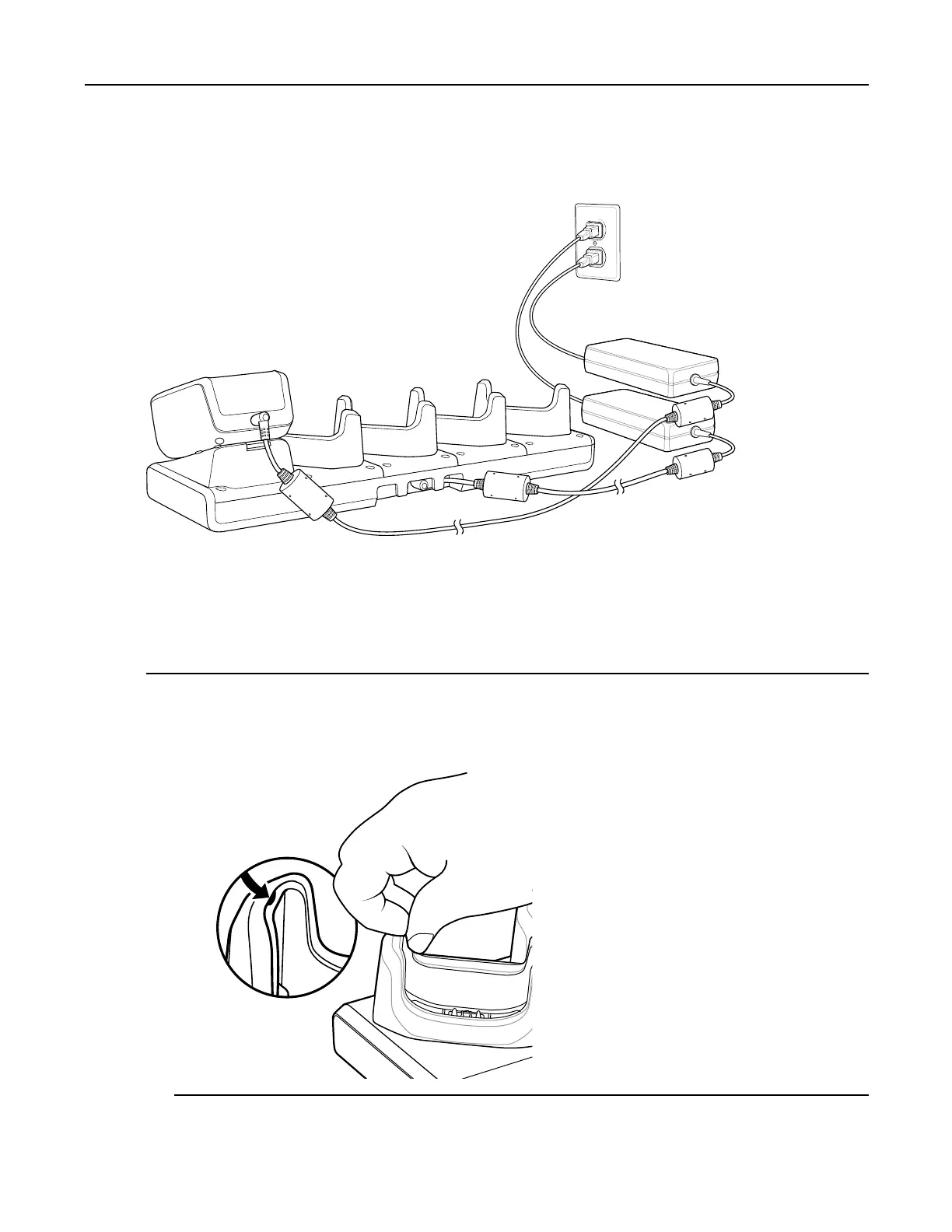
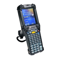
2.4.4
Removing
Cradle
Insert
Figure
2-14
Five
Slot
Charge
Only
Cradle
Power
Connections
2.4.4
Removing
Cradle
Insert
Procedure
Steps
1
W
ith
nger
nail,
grasp
insert
notch.
Figure
2-15
Grasp
Insert
Notch
MN0001
12A01
-
September
2013
2-15
42
44
Table of Contents
Main Page
Table of Contents
7
Manufacturing Label Location
18
Getting Started
19
Unpacking
19
Setup
19
Installing the Battery
19
Charging the Battery
20
Figure 1-1 Inserting the Battery
20
Powering on the MC40
21
Table 1-1 Battery Charge LED Status
21
Replacing the Battery
22
Figure 1-2 Lift Battery Latch
22
Resetting the Device
23
Performing a Soft Reset
23
Figure 1-3 Remove Battery
23
Performing a Hard Reset
24
Performing an Enterprise Reset
24
Figure 1-4 Recovery Mode Screen
25
Figure 1-5 System Recovery Screen
25
Performing a Factory Reset
26
Figure 1-6 Recovery Mode Screen
27
Figure 1-7 System Recovery Screen
27
Accessories
29
MC40 Accessories
29
Table 2-1 MC40 Accessories
29
Single Slot Charge Only Cradle
30
Single Slot Charge Cradle Setup
30
Figure 2-1 Micro USB Cable Installation
31
Figure 2-2 Single Slot Charge Only Cradle Setup
31
Removing Cradle Insert
32
Figure 2-3 Grasp Insert Notch
32
Charging Using the Single Slot Charge Only Cradle
33
Figure 2-4 Remove Insert
33
Four Slot Battery Charger
34
Figure 2-5 MC40 Battery Charging
34
Figure 2-6 Four Slot Battery Charger
35
Single Charger Setup
35
Two Charger Setup
35
Figure 2-7 Setup with 2-Way DC Cable
36
Four Charger Setup
36
Charging with the Four Slot Battery Charger
37
Figure 2-8 Setup with 4-Way DC Cable
37
Figure 2-9 Charging Batteries
38
Table 2-2 Spare Battery Charge LED Status
38
Five Slot Charge Only Cradle
39
Installing a Cup
39
Figure 2-10 Five Slot Charge Only Cradle
39
Figure 2-11 Five Slot Charge Only Cradle Cup Installation
40
Installing a Four Slot Battery Charger
41
Figure 2-12 Securing Cup to Base
41
Power to Five Slot Charge Only Cradle
42
Figure 2-13 Multi Slot Charge Only Cradle Four Slot Battery Charger Installation
42
Removing Cradle Insert
43
Figure 2-14 Five Slot Charge Only Cradle Power Connections
43
Figure 2-15 Grasp Insert Notch
43
Charing Using the Five Slot Charge Only Cradle
44
Figure 2-16 Remove Insert
44
Installing the Finger Strap
45
Figure 2-17 Charging MC40 and Spare Battery
45
Figure 2-18 Remove Battery
46
Figure 2-19 Remove Rubber Plug
46
Figure 2-20 Align Finger Strap
47
Figure 2-21 Secure Finger Strap to MC40
48
Installing the Rubber Boot
49
Figure 2-22 Install Battery
49
Figure 2-23 Rubber Boot
49
Figure 2-24 Insert MC40 into Boot
50
Figure 2-25 Pull Boot over MC40
50
USB Communication
51
Connecting to a Host Computer Via USB
51
Disconnect from the Host Computer
52
Datawedge Configuration
53
Basic Scanning
53
Using the Camera
53
Using the Imager
54
Figure 4-1 Data Capture with Camera
54
Profiles
55
Figure 4-2 Data Capture
55
Plug-Ins
56
Profiles Screen
57
Figure 4-3 Datawedge Profiles Screen
58
Figure 4-4 Profile Context Menu
58
Disabling Datawedge
59
Creating a New Profile
59
Figure 4-5 Datawedge Options Menu
59
Profile Configuration
60
Figure 4-6 New Profile Name Dialog Box
60
Bar Code Input
61
Figure 4-7 Profile Configuration Screen
61
Keystroke Output
69
MSR Input
69
Intent Output
70
Intent Overview
71
IP Output
72
Figure 4-8 IP Output Screen
74
Using IP Output with Ipwedge
74
Figure 4-10 IP Address Entry
75
Figure 4-11 Port Number Entry
75
Figure 4-9 Protocol Selection
75
Figure 4-12 Protocol Selection
76
Figure 4-13 IP Address Entry
76
Using IP Output Without Ipwedge
76
Generating Advanced Data Formatting Rules
77
Configuring ADF Plug-In
77
Figure 4-14 Port Number Entry
77
Creating a Rule
78
Figure 4-15 Advanced Data Formatting Screen
78
Defining a Rule
79
Defining Criteria
79
Figure 4-16 Rule List Screen
79
Figure 4-17 Criteria Screen
80
Defining an Action
81
Figure 4-18 Barcode Input Screen
81
Deleting a Rule
82
Order Rules List
82
Table 4-1 ADF Supported Actions
83
ADF Example
84
Deleting an Action
84
Figure 4-19 ADF Sample Screen
87
Figure 4-20 Sample Bar Code
87
Datawedge Settings
88
Figure 4-21 Formatted Data
88
Figure 4-22 Datawedge Settings Window
88
Exporting a Configuration File
89
Importing a Configuration File
89
Exporting a Profile
90
Importing a Profile File
90
Restoring Datawedge
91
Configuration and Profile File Management
91
Programming Notes
92
Overriding Trigger Key in an Application
92
Capture Data and Taking a Photo in the same Application
93
Disable Datawedge on MC40 and Mass Deploy
93
Soft Scan Feature
93
WLAN Configuration
95
Connecting to a Wi-Fi Network
95
Figure 5-1 WLAN Network Security Dialog Boxes
96
Manually Adding a Wi-Fi Network
97
Configuring for a Proxy Server
98
Configuring the Device to Use a Static IP Address
99
Figure 5-2 Proxy Settings
99
Advanced Wi-Fi Settings
100
Figure 5-3 Static IP Settings
100
Disabling 802.11D Feature
102
Remove a Wi-Fi Network
102
Administrator Utilities
103
Required Software
103
On-Device Application Installation
103
Multi-User/Applock Configuration
103
Enterprise Administrator Application
104
Creating Users
104
Figure 6-1 Enterprise Administrator Window
104
Adding Packages
105
Figure 6-2 User Manager Window
105
Creating Groups
106
Figure 6-3 Package Information Window
106
Creating Remote Authentication
107
Figure 6-4 Group Manager Window
107
Save Data
108
Exporting File
108
Figure 6-5 Authentication Window
108
Importing User List
109
Importing Group List
109
Importing Package List
110
Editing a User
110
Deleting a User
110
Editing a Group
110
Deleting a Group
111
Editing a Package
111
Deleting a Package
111
Multiuser Administrator
111
Importing a Password
112
Figure 6-6 Multiuser Administrator Screen
112
Disabling the Multi-User Feature
113
Figure 6-7 Multiuser Login Screen
113
Enabling Remote Authentication
114
Disabling Remote Authentication
114
Enabling Data Separation
115
Disabling Data Separation
115
Delete User Data
116
Capturing a Log File
117
Applock Administrator
117
Installing Groups and White Lists
118
Figure 6-8 Applock Administrator Screen
119
Enabling Application Lock
120
Disabling Application Lock
120
Manual File Configuration
120
Determining Applications Installed on the Device
122
Secure Storage
122
Installing a Key
122
Viewing Key List
123
Figure 6-9 Enter Key Dialog Box
123
Deleting a Key
124
Figure 6-10 List of Keys
124
Volumes
125
Creating a Volume Manually
125
Creating Volume Using EFS File
125
Figure 6-11 Enter Parameter to Create Volume Dialog Box
126
Mounting a Volume
126
Deleting a Volume
127
Listing Volumes
127
Unmounting a Volume
127
Encrypting an SD Card
128
Creating an EFS File
128
Off-Line Extraction Tool
129
Creating an Image
129
Mounting an Image
130
Unmounting an Image
131
Device-Config Utility
133
Figure 7-1 Select Action Window
133
Creating a Golden Configuration
134
Figure 7-2 Select an Action Window
134
Figure 7-3 Golden Configuration Window
135
Figure 7-4 Datawedge Profiles Window
136
Figure 7-5 Select Apks to Transfer Window
137
Figure 7-6 QR Code Generation Screen
138
Transferring a Golden Configuration
138
Figure 7-7 Scan QR Code Window
139
Figure 7-8 Reboot Confirmation Dialog Box
140
Returning to the Default Configuration
140
Settings
141
Location Settings
141
Screen Unlock Settings
141
Figure 8-1 Location Services Window
141
Single User Mode
142
Set Screen Unlock Using PIN
142
Figure 8-2 PIN Screen
143
Set Screen Unlock Using Password
143
Figure 8-3 Password Screen
144
Set Screen Unlock Using Pattern
144
Figure 8-4 Choose Your Pattern Screen
145
Multiple User Mode
146
Passwords
146
Button Remapping
146
Figure 8-5 Pattern Screen
146
Figure 8-6 Key Programmer Screen
147
Remapping a Button
147
Figure 8-7 Remapped Button
148
Setting the Headset Key
148
Exporting a Configuration File
149
Figure 8-8 Headset Button Remapping
149
Creating a Remap File
150
Importing a Configuration File
150
Accounts
152
Language Usage
152
Changing the Language Setting
153
Adding Words to the Dictionary
153
Keyboard Settings
153
About Device
153
PTT Express Configuration
154
Table 8-1 PPT Express Configuration File Keys
154
Importing a PTT Express Configuration File
158
Application Deployment
159
Security
159
Secure Certificates
159
Installing a Secure Certificate
160
Configuring Credential Storage Settings
160
Development Tools
160
ADB USB Setup
162
Application Installation
162
Installing Applications Using the USB Connection
162
Figure 9-1 Accept Installation Screen
163
Installing Applications Using the Android Debug Bridge
163
Mobility Services Platform
164
Uninstalling an Application
165
Updating the System
165
Figure 9-2 Downloaded Screen
165
Figure 9-3 Recovery Mode Screen
166
Upgrading the Operating System from Gingerbread to Jellybean
167
Figure 9-4 System Recovery Screen
167
Figure 9-5 Recovery Mode Screen
169
Figure 9-6 System Recovery Screen
169
Copying Applications and Configuration Files
170
Storage
170
Figure 9-7 Running Screen
171
On-Device Storage
171
Random Access Memory
171
Figure 9-8 On-Device Storage Screen
172
Internal Storage
172
Enterprise Folder
173
Application Management
173
Figure 9-9 Internal Storage Screen
173
Figure 9-10 Manage Applications Screen
174
Viewing Application Details
174
Stopping an Application
175
Changing Application Location
176
Figure 9-11 Running Applications
176
Managing Downloads
177
Maintenance and Troubleshooting
179
Maintaining the MC40
179
Battery Safety Guidelines
179
Cleaning Instructions
180
Cleaning the MC40
181
Connector Cleaning
181
Cleaning Cradle Connectors
182
Troubleshooting
183
Troubleshooting the MC40
184
Table 10-1 Troubleshooting the MC40
185
Five-Slot Charge Only Cradle CRDUNIV-40-5000R Troubleshooting
186
Single-Slot Charge Cradle Troubleshooting
186
Table 10-2 Troubleshooting the Single-Slot Charge Cradle
186
Table 10-3 Troubleshooting the Five-Slot Charge Only Cradle
186
Four-Slot Battery Charger SACMC40XX-4000R Troubleshooting
187
Table 10-4 Troubleshooting the Four-Slot Battery Charger
187
Technical Specifications
189
MC40 Technical Specifications
189
Table 11-1 MC40 Technical Specifications
189
MC40 Decode Zone
191
Table 11-2 SE4500-DL Decode Distances
192
Figure 11-1 SE4500-DL Decode Zone
192
MC40 Connector Pin-Outs
193
Table 11-3 Headset Connector Pin-Outs
193
Figure 11-2 Headset Connector
193
Table 11-4 Power Connector Pin-Outs
194
Table 11-5 Micro-B USB Connector Pin-Outs
194
Figure 11-3 Power Connector
194
Figure 11-4 Micro-B USB Connector
194
Single-Slot Charge Cradle CRDMC40XX-1000R Technical Specifications
195
Five-Slot Charge Only Cradle CRDUNIV-40-5000R Technical Specifications
195
Table 11-6 Single-Slot Charge Cradle Technical Specifications
195
Table 11-7 Five-Slot Charge Only Cradle Technical Specifications
195
Four-Slot Battery Charger SACMC40XX-4000R Technical Specifications
196
Table 11-8 Four-Slot Battery Charger Technical Specifications
196
Keypad Remap Strings
199
Table 12-1 Remap Key Event/Scancodes
199
Other manuals for Motorola MC40
User Manual
166 pages
User Guide
126 pages
Quick Start Guide
4 pages
Related product manuals
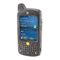
Motorola MC75
202 pages
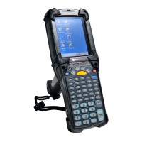
Motorola MC67
224 pages
Motorola MC2180
106 pages
Motorola MC9190
10 pages
Motorola MC32N0
182 pages
Motorola MC1000
80 pages
Motorola MC3090Z
62 pages
Motorola MC9500-K
284 pages
Motorola MC9190-G
174 pages
Motorola MC3100-S
2 pages
Motorola MC2100 Series
2 pages
Motorola MC31XX Series
186 pages