EasyManuals Logo

Muratec F-525 User Manual

Muratec F-525
383 pages
To Next Page IconTo Next Page
To Previous Page IconTo Previous Page
Page #381 background imageLoading...
Page #381 background image
6-9
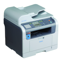
4. Attach two spacers to the main board.
5. Attach the Modem PCB to the spacers and screw the right side of the board to the machine frame
using two screws. (Screw A)
6. Attach the NCU PCB onto the Main PCB using four screws. (Screw B)
7. Connect the harness to the NCU PCB.
8. Clamp the harness to the NCU PCB’s bracket.
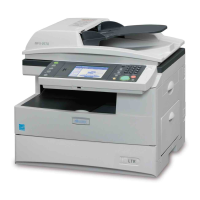
9. Reattach the covers and the harness.
10. Wind the telephone line around the ferrite core and connect it to Line 2.
11. Attach the “Line 2” label above the plug.
LINE2

Table of Contents

Other manuals for Muratec F-525

Questions and Answers:

Question and Answer IconNeed help?

Do you have a question about the Muratec F-525 and is the answer not in the manual?

Muratec F-525 Specifications

General IconGeneral
BrandMuratec
ModelF-525
CategoryAll in One Printer
LanguageEnglish

Related product manuals