OMICRON 125
Off-service diagnostic methods
2. Make sure that all cable connectors are clean and dry before being tightly connected.
3. Connect CIBANO 500 to the main contact of the circuit breaker for one phase according to the wiring
diagram displayed in Primary Test Manager.
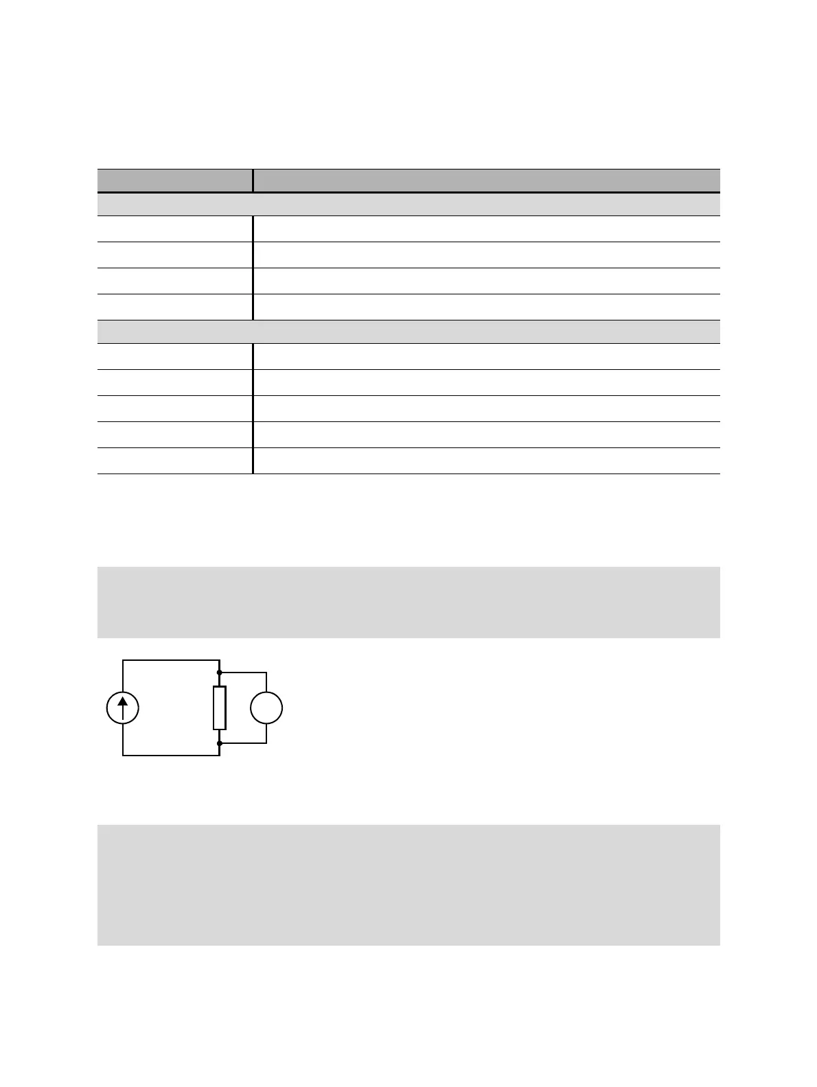
Figure 17-5: Principal scheme of the contact resistance test
Table 17-2: Hardware configuration options of CIBANO 500
CIBANO 500 Option
A-OUTPUT / INPUT (CAT III / 300 V)
A1 Current +
A2 Current +
A3 Current +
AN Not connected in this test
B-OUTPUT / INPUT (CAT III / 300 V)
B1 Current –
B2 Current –
B3 Current –
BN Voltage Sense –
B4 Voltage Sense +
Tips & Tricks: For easy connection use the delivered multi-core cables and connect the end with the
short wires to the CIBANO 500 sockets according to the short-wire labels. Connect the cable end with
the long wires according to the wiring diagram to the corresponding Kelvin clamp. The black AN cable
is not needed for this test and remains unconnected.
Tips & Tricks: The delivered Kelvin clamp is the perfect solution for connecting to a massive conductor
like a copper busbar or similar. We recommend using only the red connectors of the Kelvin clamps
(which is the current path) when connecting to the contact fingers of a MV circuit breaker. Use a
separate clamp for the voltage sense cables (BN and B4) which can be mounted closer to the MV
circuit breaker contact. If the connection is set up properly the resistance decreases when the voltage
sense clamps are connected closer to the circuit breaker contact. The polarity of connection does not
matter for this test.

 Loading...


