CIBANO 500 PTM User Manual
26 OMICRON
4.1 Voltage operating mode
The following figure explains the CIBANO 500 voltage operating mode.
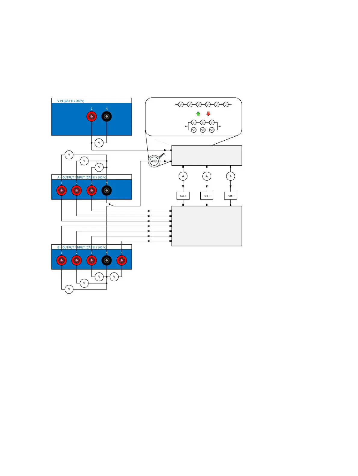
Figure 4-3: The CIBANO 500 voltage operating mode
Figure 4-3: "The CIBANO 500 voltage operating mode" shows the switching of the internal amplifiers in
the voltage operating mode. In this case seven channels are available: A1…A3 and B1…B4. Three
channels of these seven channels can be used synchronously but all either of the section A or the
section B. You cannot use the outputs of both sections at the same time but only sequentially, one after
each other.
The driving source of the channel can be either the internal amplifiers or an external source connected
to the VIN input of CIBANO 500. Depending on the settings of the firmware the amplifier matrix in Figure
4-3 connects inputs of the IGBTs (integrated gate bipolar transistors) to either the internal amplifier or
the external source. The socket matrix then routes the output of each of the three IGBTs to the seven
channels on the CIBANO 500 side panel. To apply a voltage to a socket the corresponding IGBT is
closed.
Note: There is a certain voltage drop across the IGBTs which is not controlled by the source due to the
design related issues of the device.
High-range
voltage mode
Half current
double voltage
Double current
half voltage
Low-range
voltage mode
Input matrix 2×3 (Each of the three
outputs is connected to either an
internal amplifier or external source.)
Output matrix 3×7 (Each of the three
inputs is routed to only one of the
seven outputs.)

 Loading...


