OMICRON 307
Technical data
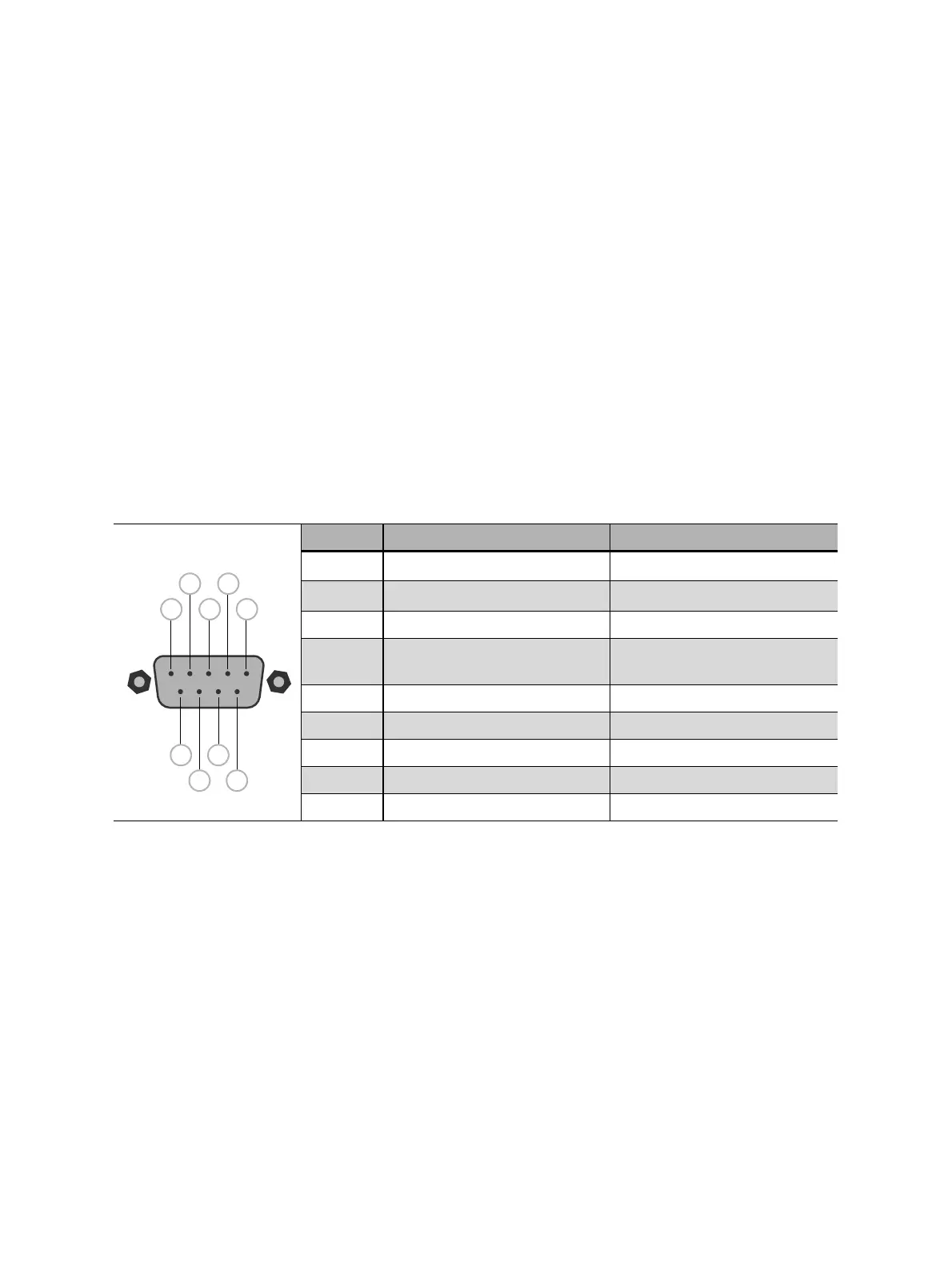
21.4.2 SAFETY 1 and SAFETY 2 connector pinouts
SAFETY 1 and SAFETY 2 connector pinouts differ slightly (see Table 21-17: "SAFETY 1 and
SAFETY 2 pin assignment", Figure 21-3: "SAFETY 1 (primary) connector schematics" and
Figure 21-4: "SAFETY 2 (secondary) connector schematics" later in this section).
21.4.3 External START button connection
SAFETY 1 (primary) connector can be used to connect an external START button to allow remote
control of CIBANO 500. If an external START button is used, the switch must fulfill the following
requirements:
•R
off
(open resistance) > 1 MΩ
•R
on
(close resistance) < 10 Ω
•I
switch
(switching current) < 1.5 mA
•V
switch
(switching voltage) < 15 V
Table 21-17: SAFETY 1 and SAFETY 2 pin assignment
Pin no. SAFETY 1 (primary) SAFETY 2 (secondary)
1
1
1. Typical output pin 1 and pin 2 for SAFETY 1 and SAFETY 2 each: 10 V…14 V/max. 400 mA
Warning light green Warning light green
2
1
Warning light red Warning light red
3*
Start button IN (n/o) Start button OUT (n/o)
4*
Common start n/o +
emergency stop
Common start n/o +
emergency stop
5*
Emergency stop Emergency stop
6*
Ground Ground
7*
Ground Ground
8*
Start button IN (n/c) Start button OUT (n/c)
9*
Ground Ground

 Loading...


