OMICRON 181
Off-service diagnostic methods
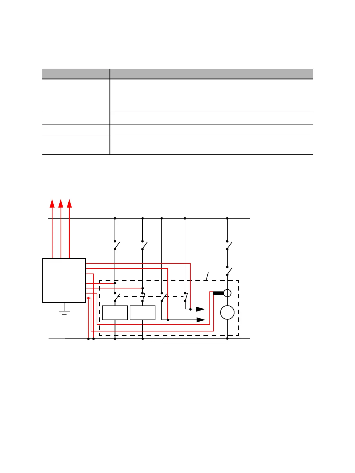
8. Connect CIBANO 500 to the trip and close coils of the circuit breaker for all phases according to the
wiring diagram displayed in Primary Test Manager and the following figure.
Figure 17-24: Typical measurement setup for the Timing test
For the circuit breakers with one drive for all three phases connect the trip coil to B1, the close coil to
B2, and the common connection of the trip and close coils (typically the battery minus) to BN. In general,
the motor of the HV circuit breakers remains connected to the station battery throughout the test and a
current clamp connected to BN and B4 is used to record the motor current.
Combine Click the Combine check box to combine the channels of the CB MC2
module. The combined CB MC2 channels can both be either active or
inactive. The measurement results are labeled with the name of channel 1,
and the voltage is only measured on channel 1.
Ch.name
1
Editable name of the CB MC2 channel
Charge Indicates the charge status of the CB MC2 module.
LED Click the LED symbol to identify the connected CB MC2 module by flashing
LED.
1. Permanently stored in the CB MC2 memory. You can, for example, mark your CB MC2 modules with the colored stickers and
name them according to the colors. You can also rename the CB MC2 modules depending on the connection point.
Table 17-39: Hardware configuration options of the CB MC2 module (continued)
CB MC2 Option
Trip coil
–
CIBANO 500
A1
A2
AN
B1
B2
BN
+
AUX 1 AUX 2
B4
M
Circuit
breaker
EXTERNAL
MODULES
Close coil
3 × CB MC2

 Loading...


