CIBANO 500 PTM User Manual
190 OMICRON
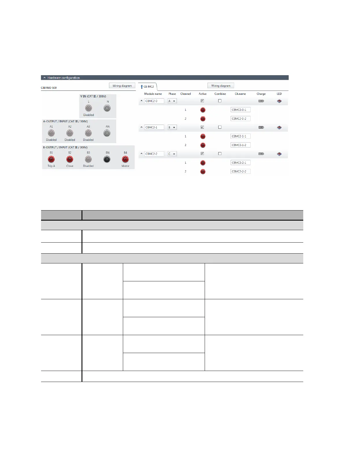
7. In the Hardware configuration area, set the hardware configuration and check whether Primary
Test Manager recognized all connected CB MC2 modules.
Figure 17-25: Hardware configuration of the Dynamic Contact Resistance test
Table 17-47: Hardware configuration options of CIBANO 500
CIBANO 500 Option
V IN (CAT III / 300 V)
1
External source, Trigger IN
1
or Disabled
N Neutral connection of VIN
A-OUTPUT / INPUT (CAT III / 300 V)
A1 AUX 1
Dry contact
(potential-free)
Close A, Motor A, Trigger IN
1
or
Disabled
Wet contact
(with potential)
A2 AUX 2
Dry contact
(potential-free)
Close B, Motor B, Trigger IN
1
or
Disabled
Wet contact
(with potential)
A3 AUX 3
Dry contact
(potential-free)
Close C, Motor C, Trigger IN
1
or
Disabled
Wet contact
(with potential)
AN Common neutral connection for outputs/inputs in group A

 Loading...


