OMICRON 193
Off-service diagnostic methods
8. Connect CIBANO 500 to the trip and close coils of the circuit breaker for all phases according to the
wiring diagram displayed in Primary Test Manager and the following figure.
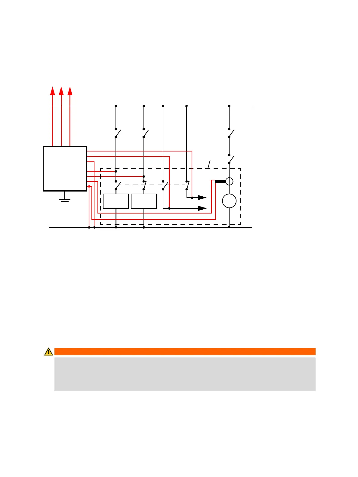
Figure 17-26: Typical measurement setup for the Dynamic Contact Resistance test
For circuit breakers with one drive for all three phases connect the trip coil to B1, the close coil to B2,
and the common connection of the trip and close coils (typically the battery minus) to BN. The HV circuit
breaker’s motor remains generally connected to the station battery throughout the test and a current
clamp connected to BN and B4 is used to record the motor current.
Note: Connect the current clamp neutral directly to CIBANO 500 and not to the other end of the neutral
cable to avoid measurement errors due to the voltage drop on the cable. Alternatively you can supply
the motor from CIBANO 500 if you want or no station battery is available.
Circuit breakers with three drives are either tested phase by phase (see 17.2.3 "Testing circuit breakers
with CIBANO 500 and the CB MC2 modules" on page 165) or you can connect the three trip and close
signals together. If you want to record the supply current for three coils simultaneously you can configure
the sockets by clicking them.
WARNING
Death or severe injury caused by high voltage or current possible
► If you use the station battery to supply the motor or the coils via CIBANO 500, do not connect
the cables to the station battery before they are connected to CIBANO 500.
► Always connect the cables first to grounded CIBANO 500 and then to the station battery.
Trip coil
–
CIBANO 500
A1
A2
AN
B1
B2
BN
+
AUX 1 AUX 2
B4
M
Circuit
breaker
EXTERNAL
MODULES
Close coil
3 × CB MC2

 Loading...


