OMICRON 207
Off-service diagnostic methods
4. Make sure that all cable connectors are clean and dry before being tightly connected.
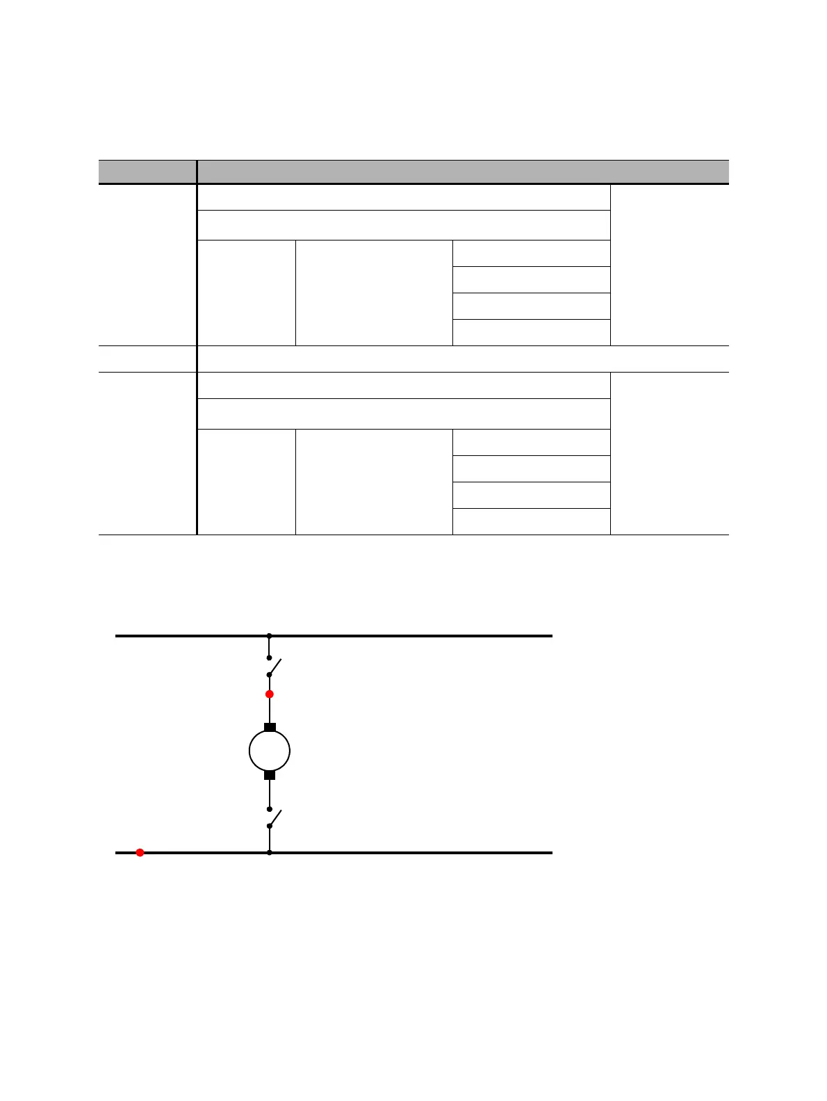
5. Connect CIBANO 500 to the motor of the circuit breaker according to the wiring diagram displayed in
Primary Test Manager and the following figure.
Figure 17-29: Connecting CIBANO 500 to the circuit breaker for the Motor Current test (The end position
switch opens when the spring is charged.)
Measurement
To perform a measurement:
1. In the Settings and conditions area, enter the settings of the Motor Current test.
B3
Supply
or Disabled
Trigger IN
1
I clamp 3 Motor
all
Phase A
Phase B
Phase C
BN Neutral connection of outputs in group B
B4
Motor
or Disabled
Trigger IN
1
I clamp 4 Motor
all
Phase A
Phase B
Phase C
1. Trigger signal starting the measurement
Table 17-60: Hardware configuration options of CIBANO 500 (continued)
CIBANO 500 Option
+
Common (for example, BN)
Motor (for example, B4)
End position switch
–
Motor

 Loading...


