CIBANO 500 PTM User Manual
260 OMICRON
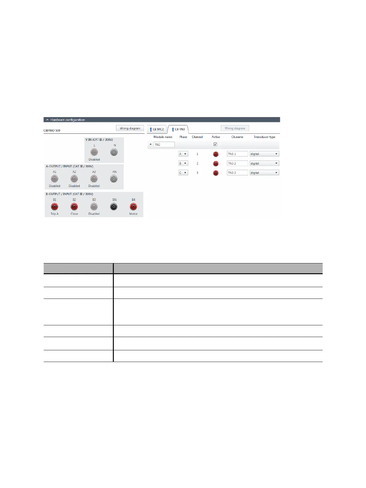
8. In the Hardware configuration area, set the hardware configuration and check whether Primary
Test Manager recognized all connected CB TN3 modules.
The following figure shows the hardware configuration of CIBANO 500 with the EtherCAT
®
module
with one CB MC2 and one CB TN3 module connected. For the hardware configuration options of
CIBANO 500 and the CB MC2 module, see Table 17-47: "Hardware configuration options of
CIBANO 500" on page 190 and Table 17-48: "Hardware configuration options of the CB MC2
module" on page 192.
Figure 17-55: Example of the hardware configuration of the Dynamic Contact Resistance test for
measuring the main contact travel during operation
Table 17-91: Hardware configuration options of the CB TN3 module
CB TN3 Option
Module name
1
1. Permanently stored in the CB TN3 memory. You can, for example, mark your CB TN3 modules with the colored stickers and
name them according to the colors. You can also rename the CB TN3 modules depending on the connection point.
Editable name of the CB TN3 module
Phase Phase to which the CB TN3 module is connected
Channel
1
Editable name of the CB TN3 channel.
Click the socket symbol to activate or deactivate the channel depending on
the connections made.
Active Click the socket symbol to activate or deactivate the channel.
Ch.name
1
Editable name of the CB TN3 channel
Transducer type Type of the connected transducer: digital or analog

 Loading...


