CIBANO 500 PTM User Manual
278 OMICRON
Current clamp settings
You must configure the current clamps before connecting them to the circuit breaker under test. The
following figure shows the setting controls of OMICRON current clamps.
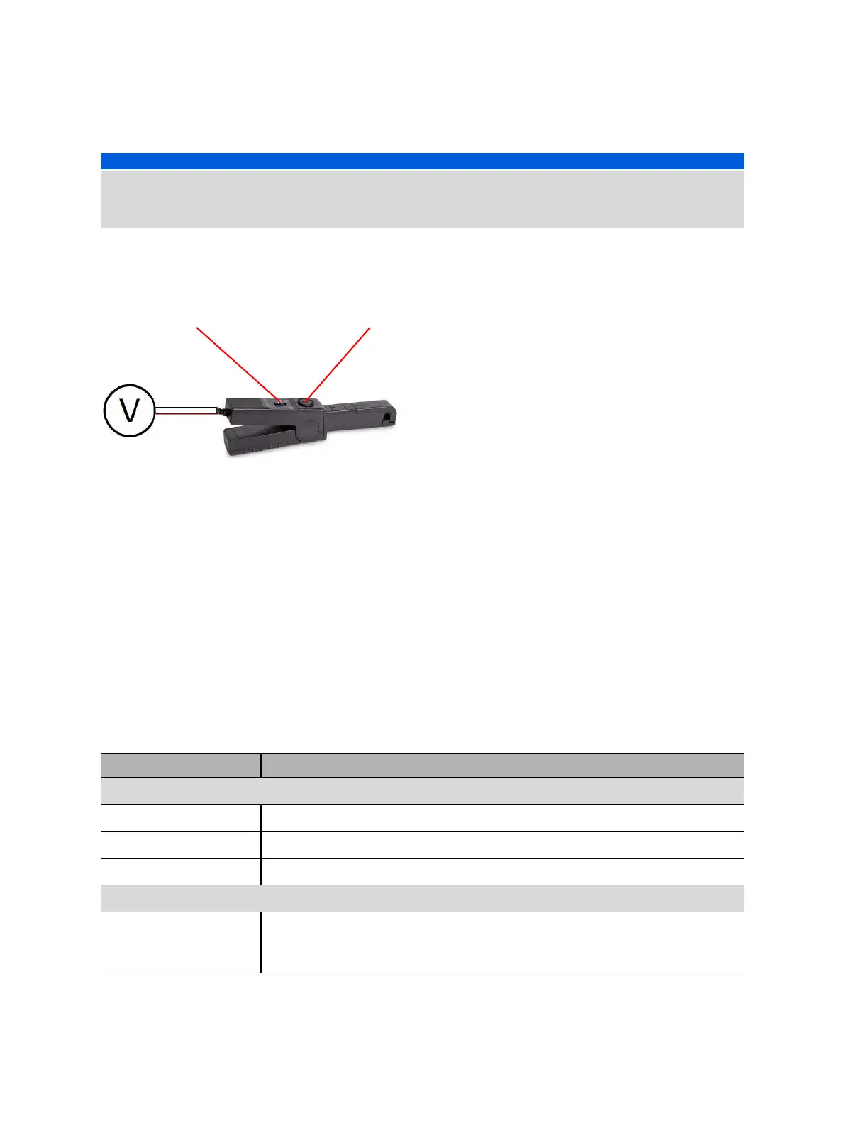
Figure 18-4: Setting controls of OMICRON current clamps
To configure the current clamps:
1. Set the current clamp ratio (ratio of the voltage output to the measured current). Typically, the current
clamp ratio is 100 mV/A for measuring current on the secondary side of a metering current
transformer.
2. Adjust the null point of the current clamp by turning the zero adjustment wheel until a voltage meter
connected to the current clamp output shows 0 V.
Measurement
To perform a measurement:
1. In the Settings and conditions area, enter the settings of the First Trip test.
NOTICE
Equipment damage or loss of data possible
► Never connect CIBANO 500 between the respective AUX contacts of the trip and close coils and the
coils themselves since these contacts assure that the voltage is not applied too long to the coils.
Table 18-7: Settings of the First Trip test
Setting Description
Current clamp settings
Channel Group B I/O socket
Ratio Current clamp ratio
I max Maximum current of the selected probe range
Trigger setting
Threshold Threshold value of the trigger signal
The measurement starts if the trigger signal rises above (rising edge) or falls
below (falling edge) the threshold.
Ratio selection Zero adjustment wheel

 Loading...


