CIBANO 500 PTM User Manual
324 OMICRON
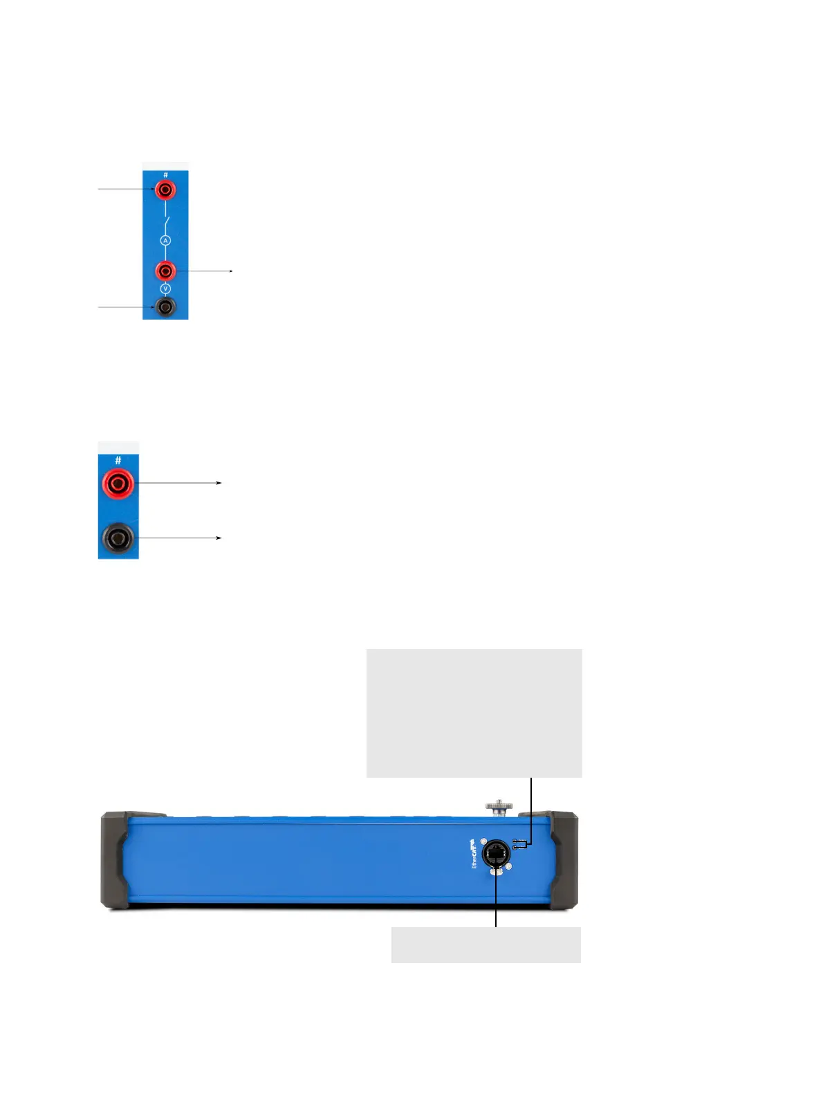
The following figures show the output and input channel configurations.
Figure 22-6: Output channel configuration
The contacts of the output channels are controlled by CIBANO 500 according to the specified test
sequence. Each output channel has an integrated voltage and current measurement. Because of the
integrated voltage measurement, the output channels can also be used to detect the state of an auxiliary
contact. The output channels are externally supplied, for example, via the B3/BN output of CIBANO 500.
Figure 22-7: Input channel configuration
The input channels are used to detect the state of an auxiliary contact. These contacts can have a
voltage supplied to them (wet) or can be potential free (dry).
Figure 22-8: Bottom view of the IOB1 module
Supply +
Supply –
To coil or motor
Aux. contact +
Aux. contact –
Two green LEDs indicating the EtherCAT
®
state.
RUN: Signals the state of the EtherCAT
®
state machine.
L/A: Signals the state of the physical link
and activity on this link.
LEDs with the same functionality are also
on the side panel of CIBANO 500 (see
3.2.2 "Side panel" on page 18.)
EtherCAT
®
connector for connecting
the IOB1 to CIBANO 500

 Loading...


