88
Connecting Communications Cables to General-purpose Slaves Section 5-2
the other lines, but it is harder than the mesh shield and should be easily
identified.
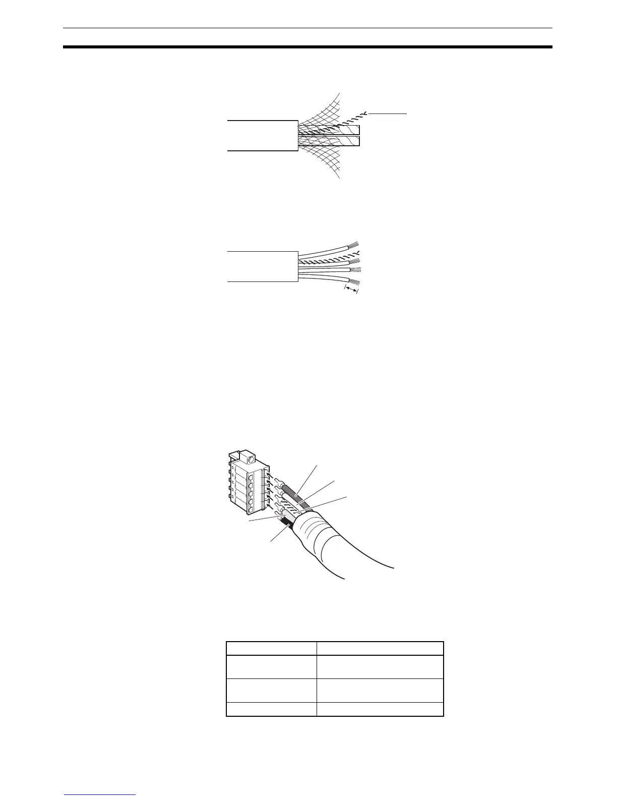
3. Remove the exposed mesh shield, remove the aluminum tape from the sig-
nal and power lines, and strip the covering from the signal and power lines
to the proper length for the crimp terminal connectors. Twist together the
wires of each of the signal and power lines.
4. Attach the crimp terminals to the lines and then cover any exposed areas
of the cable and lines with electrician's tape or heat-shrinking tubes.
5. Orient the connector properly, loosen the line set screws, and then insert
the lines in order: Red, white, shield, blue, and then black.
6. Connectors without set screws do not require lines to be secured with
screws as with previous connectors. Push up the orange tab and then in-
sert each line into the back of each hole.
Release the orange lever after inserting the lines, and gently pull each line
to check that it is securely connected to the connector.
There are colored stickers provided on the Master Unit and Slaves that
match the colors of the lines to be inserted. Check that the colors of the
lines and stickers match when wiring the connectors.
Note The colors used are as follows:
Color Signal
Red Power line, positive voltage
(+V)
White Communications line, high
(CAN H)
--- Shield
Shield wire
Strip to match
the crimp
terminals.
Red (+V)
White
(CAN H)
Shield
Black (
−V)
Blue
(CAN L)

 Loading...


