97
Remote I/O Terminals with Transistors Section 5-5
ates as an I/O Unit.)
Sensor Connector models: DRT2-MD16S(-1)
3-tier I/O Terminal Block models: DRT2-@D16TA(-1)
MIL Connector models: DRT2-@D16ML(X)(-1), DRT2-@D32ML(-1),
DRT2-@D32B(-1), and DRT2-@D32BV(-1)
Screw-less Clamp models: DRT2-@D@@SL(-1) and DRT2-@D@@SLH(-1)
2. The Peak Operation Time and Error History functions are supported by the
following models:
3-tier I/O Terminal Block models: DRT2-@D16TA(-1)
MIL Connector models: DRT2-@D16ML(X)(-1), DRT2-@D32ML(-1),
DRT2-@D32B(-1), and DRT2-@D32BV(-1)
Screw-less Clamp models: DRT2-@D@@SL(-1) and DRT2-@D@@SLH(-1)
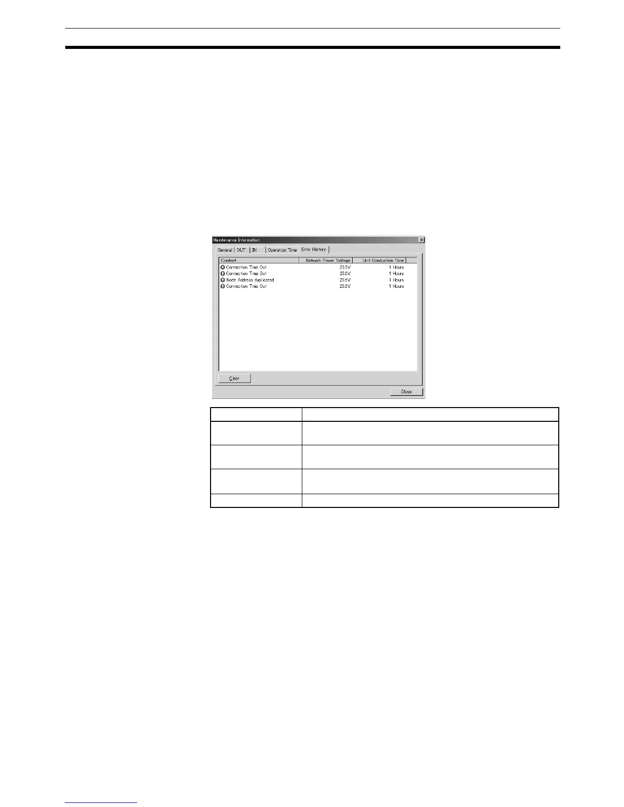
Error History Window
Note The Unit Conduction Time display is supported by the following models:
3-tier I/O Terminal Block models: DRT2-@D16TA(-1)
MIL Connector models: DRT2-@D16ML(X)(-1), DRT2-@D32ML(-1), DRT2-
@D32B(-1), and DRT2-@D32BV(-1)
Screw-less Clamp models: DRT2-@D@@SL(-1) and DRT2-@D@@SLH(-1)
5-5 Remote I/O Terminals with Transistors
5-5-1 Node Address, Baud Rate, and Output Hold/Clear Settings
This section describes the Slaves' node address setting, baud rate settings,
and hold/clear outputs for communications error settings. These settings are
made as follows:
Node address setting: Rotary switch
Baud rate setting: Automatic follow-up
Output hold/clear setting: Software switch
Item Description
Content Displays the contents of the communications errors that
occurred.
Network Power Volt-
age
Displays the power supply voltage being supplied when the
error occurred.
Unit Conduction
Time
Displays the total time that the network power supply had
been ON when the error occurred. DRT2-TS04
@ only)
Clear Button Clears the error history.

 Loading...


