255
Advanced Environment-resistive Terminals Section 6-4
6-4-4 Environment-resistive Terminals with 8 Transistor Outputs (IP67):
DRT2-OD08C (NPN) and DRT2-OD08C-1 (PNP)
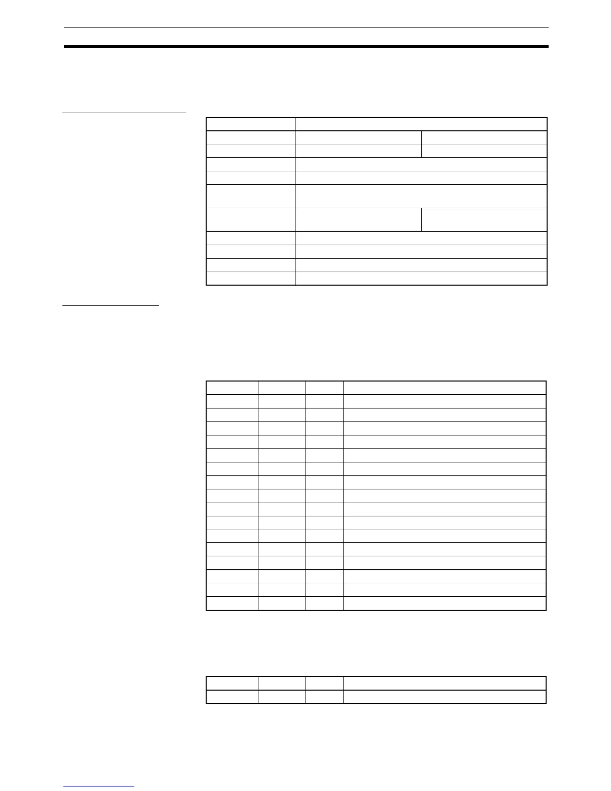
Output Specifications
Status Indicators
I/O Status Indicators The I/O status indicator displays and their meanings are shown in the follow-
ing table. Refer to the following section on names of components and func-
tions for details on the location of the I/O status indicators. In the indicator
name “1-A,” the “1” indicates the connector number, and the “A” indicates that
it is an I/O status indicator.
Note Although the connectors are numbered from 1 to 8, the input bits are num-
bered from 0 to 7. (The inputs are also numbered from 0 to 7 in the Configura-
tor displays.)
I/O Power Supply Status
Indicator
Item Specifications
Model DRT2-OD08C DRT2-OD08C-1
Internal I/O common NPN PNP
Output points 8 points
Rated output current 1.5 A/point, 8.0 A/common
I/O power supply
voltage
20.4 to 26.4 V DC (24 V DC, −15 to +10%)
Residual voltage 1.2 V max. (at 1.5 A between
each output terminal and G)
1.2 V max. (at 1.5 A between
each output terminal and V)
Leakage current 0.1 mA max.
ON delay time 0.5 ms max.
OFF delay time 1.5 ms max.
Number of circuits 8 points with one common
Indicator Color Status Meaning
1-A Yellow ON Output 0 is ON.
1-B Red ON The load of output 0 has shorted.
2-A Yellow ON Output 1 is ON.
2-B Red ON The load of output 1 has shorted.
3-A Yellow ON Output 2 is ON.
3-B Red ON The load of output 2 has shorted.
4-A Yellow ON Output 3 is ON.
4-B Red ON The load of output 3 has shorted.
5-A Yellow ON Output 4 is ON.
5-B Red ON The load of output 4 has shorted.
6-A Yellow ON Output 5 is ON.
6-B Red ON The load of output 5 has shorted.
7-A Yellow ON Output 6 is ON.
7-B Red ON The load of output 6 has shorted.
8-A Yellow ON Output 7 is ON.
8-B Red ON The load of output 7 has shorted.
Indicator Color Status Meaning
AUX PWR Green ON I/O power is being supplied.

 Loading...


