231
Screw-less Clamp Terminals Section 5-7
Note 1. The I/O power supply’s right-side and left-side V terminals, and the right-
side and left-side G terminals, are not connected internally. Supply power
separately between V and G on the right and left sides respectively.
2. When using inductive loads (such as solenoid valves), use a load with a
built-in diode to absorb reverse power or attach a diode externally
3. Wire colors have been changed according to revisions in the JIS standards
for photoelectric and proximity sensors. The colors in parentheses are the
wire colors prior to the revisions.
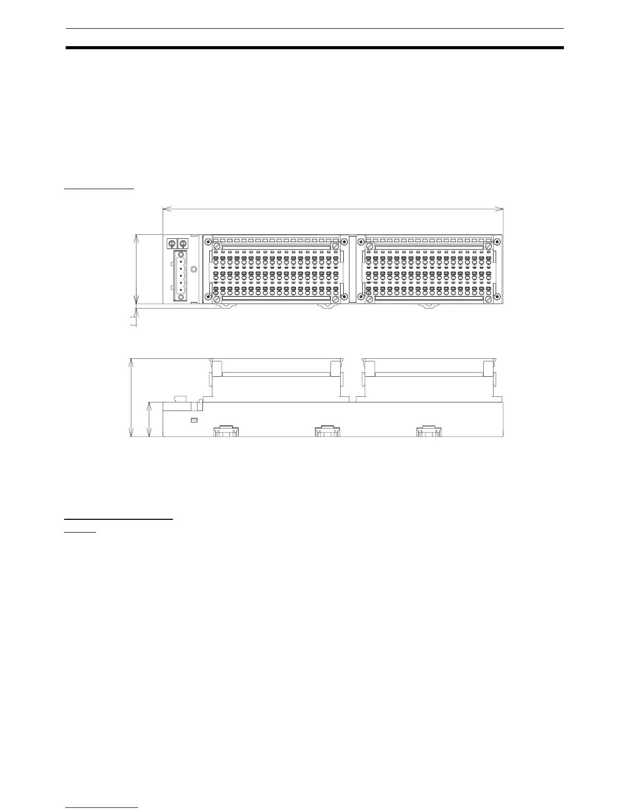
Dimensions
5-7-9 Mounting to a Control Panel
A Remote I/O Terminal (either a Basic Unit or Expansion Unit) can be
mounted to a control panel as shown below.
Mounting to a DIN
Track
Mount a 35-mm DIN Track to the rear panel of the Slave. Firmly insert the
Slave into the DIN Track while pulling down the DIN Track mounting hooks on
the rear panel with a screwdriver. Secure the Slave on the right and left sides
between a pair of end plates.
50
245
56.4
25
3

 Loading...


