27
Starting Communications Section 2-4
2-4 Starting Communications
After setting and wiring the hardware, turn ON the communications power
supply, the internal power supply of each node, and the I/O power supply, and
then start communications using the following procedure.
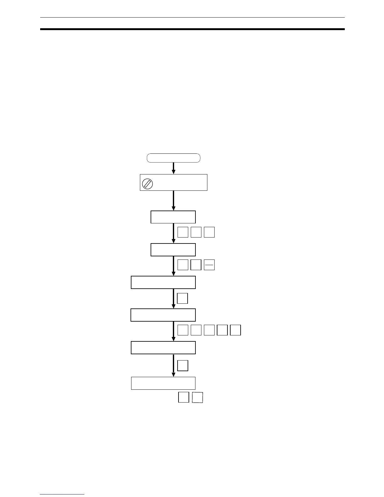
2-4-1 Creating I/O Tables for the Master Unit
I/O tables must be created in the CPU Unit to distinguish between the different
Slaves mounted to the PLC. Turn ON the PLC to which the Master Unit is
mounted, connect the Peripheral Devices to the PLC, and create the I/O
tables. After the I/O tables have been created, turn OFF the power to the PLC.
The following example shows the procedure for creating I/O tables using a
Programming Console. For details on creating I/O tables, refer to the opera-
tion manual for the Peripheral Device being used.
PROGRAM
000000 CT00
CH
*DM
9 7 1 3
0
00000IOTBL WRIT
OK
<PROGRAM>
PASSWORD!
00000IOTBL ?
?-?U=
00000IOTBL WRIT
????
00000IOTBL WRIT
9713
CLR
MONTR
CLR
FUN
SHIFT
CHG
WRITE
WRITE
CLR
Turn ON the power to the
Master Unit
Switch the CPU Unit of the
Master Unit to PROGRAM
mode.

 Loading...


