143
Remote I/O Terminals with Transistors Section 5-5
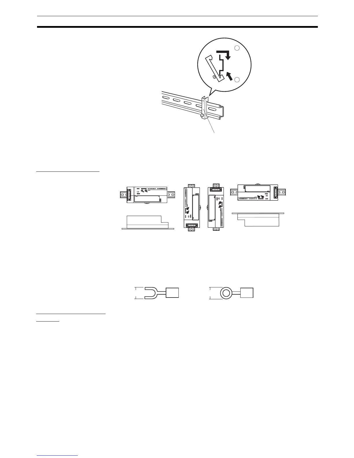
Note Always attach an End Plate to both ends of Slaves connected to the DIN
Tra c k .
Mounting Direction Unless specific restrictions are given for the Slave, it can be mounted in any of
the following six directions.
5-5-17 Wiring the I/O Power Supply and I/O Lines
The I/O power supplies and I/O lines are all wired to M3 screw terminals.
Connect M3 crimp terminals to the cables and then connect them to the Ter-
minal Block.
Tighten the screws to a torque of 0.5 N·m.
Wiring the I/O Power
Supply
Refer to the wiring details for Slave for information on the terminal arrange-
ment at the terminal block.
Connect an I/O power supply to the Expansion Unit if required. (Refer to 5-5-2
Increasing I/O Using an Expansion Unit.)
1
2
End Plate
6.0 mm max.
6.0 mm max.

 Loading...


