89
Connecting Communications Cables to General-purpose Slaves Section 5-2
Note Secure the DeviceNet cable near the Unit to prevent any force from being
applied to the Unit’s connector.
Precautions
Recommended Crimp
Terminals
PHOENIX CONTACT, A-/AI-series Crimp Terminals
OMRON XW4Z-00C
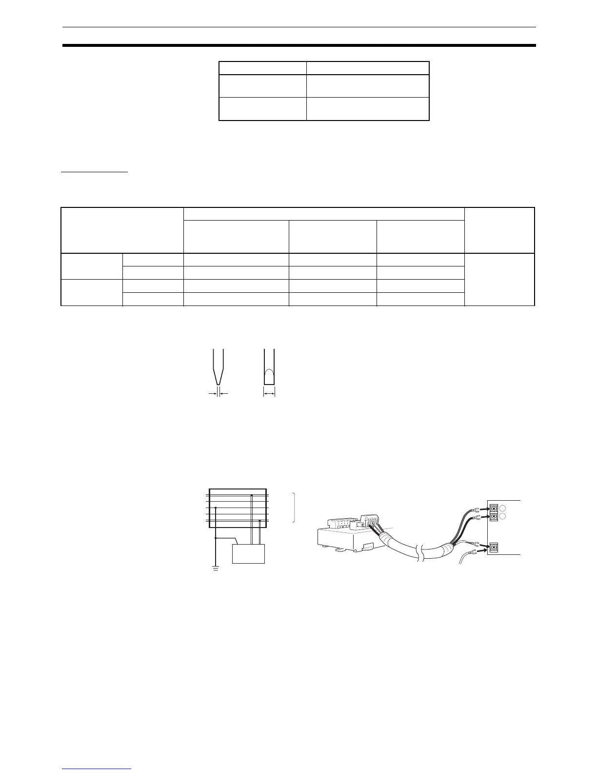
Screwdriver for Fastening
Line Set Screws
The end of the screwdriver has the following dimensions.
Supplying
Communications Power
Using T-branch Taps
Connect the +V and
−V of the power lines to the connectors in the same way
as for communications cables. If the communications power supply is in one
location only, connect a shield to the connectors when securing them, and
ground to 100
Ω max.
5-2-2 Connecting Communications Cables to the Nodes
Align the node connector with the cable connector and fully insert the project-
ing part of the cable connector into the node connector.
Depending on the type of Slave used, the connectors are secured with screws
or there is no component for securing the connectors. Always secure the con-
Blue Communications line, low
(CAN L)
Black Power line, negative voltage
(−V)
Color Signal
Cable type Connector type Applicable tool
XW4B-05C1-H1-D
XW4B-05C1-V1R-D
MSTB2.5/5-ST-5.08AU
XW4B-05C4-TF-D
XS4B-05C4-T-D
XW4G-05C1-H1-D
XW4G-05C4-TF-D
Thin Cable Signal line AI 0.25-6BU AI 0.25-8YE AI 0.25-8YE CRIMPFOX
ZA3
Power line AI 0.5-6WH AI 0.5-10WH AI 0.5-10WH
Thick Cable Signal line A1-6 A1-10 A1-10
Power line AI 2.5-8BU AI 2.5-10BU AI 2.5-10BU
3.5 mm0.6 mm
Side View Front View
+
−
FG
CAN L
V
−
V+
V
−
V+
FG
CAN H
T-branch Tap or Power
Supply Tap
Communications
power supply
Ground (100 Ω max.)
Power supply with cable grounded
(one location only)
Communications
cable
Shield
Ground
(100
Ω max.)
Communications
power supply

 Loading...


