205
Screw-less Clamp Terminals Section 5-7
5-7-3 I/O Indicators
The I/O indicators show the ON/OFF status of inputs and outputs and the
error status of connected devices.
5-7-4 Screw-less Clamp Terminals with 16 Transistor Inputs
Input Specifications
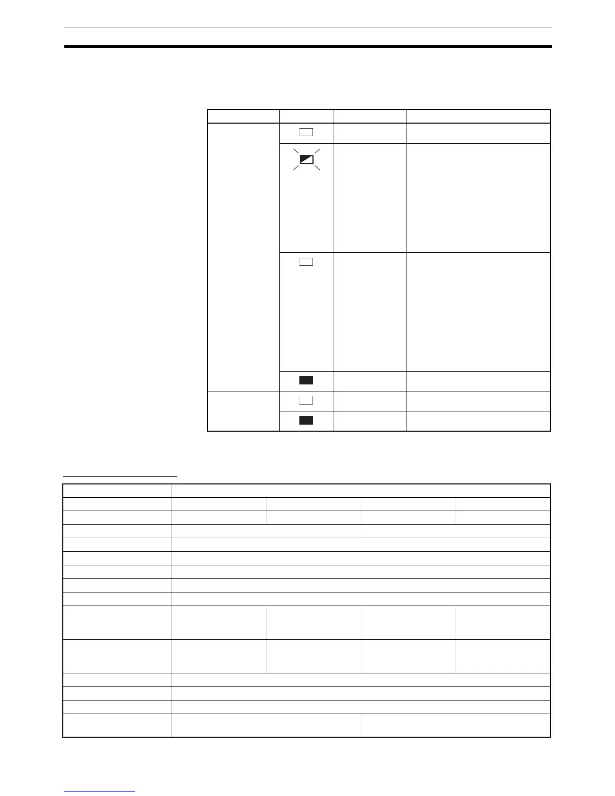
Indicator name Status Color Meaning (main error)
0 to 15
(Display for
each contact)
Yellow Lit when input or output is ON.
Red Lit when error is detected.
Output: External load disconnec-
tion
Input: Sensor disconnection
Clear as follows:
Output: For manual recovery, clear
error and then restart. For auto-
matic recovery, clear error.
Input: Clear error.
Red Lit when error is detected.
Output: External load short-circuit
(for DRT2-OD16SLH(-1) only)
Input: Sensor power supply short-
circuit
Clear as follows:
Output: For manual recovery, clear
error and then restart. For auto-
matic recovery, clear error.
Input: Clear error.
OFF Lit when input or output is OFF.
I/O Green I/O power is being supplied.
OFF I/O power is not being supplied.
Item Specification
Model DRT2-ID16SL DRT2-ID16SL-1 DRT2-ID16SLH DRT2-ID16SLH-1
Internal I/O common NPN PNP NPN PNP
Input points 16 points
I/O power supply voltage 20.4 to 26.4 V DC (24 V DC, −15% to 10%)
Input current 6.0 mA max./point at 24 V DC, 3.0 mA min./point at 17 V DC
Input resistance 4 kΩ
ON delay time 1.5 ms max.
OFF delay time 1.5 ms max.
ON voltage 15 V DC min.
(between each input
terminal and V)
15 V DC min.
(between each input
terminal and G)
15 V DC min.
(between each input
terminal and V)
15 V DC min.
(between each input
terminal and G)
OFF voltage 5 V DC max.
(between each input
terminal and V)
5 V DC max.
(between each input
terminal and G)
5 V DC max.
(between each input
terminal and V)
5 V DC max.
(between each input
terminal and G)
ON current 3 mA min.
OFF current 1 mA max.
Number of circuits 8 points with one common
Power supply short-cir-
cuit protection
--- Operates at 50 mA/pt. min.

 Loading...


