25
Setting and Wiring Hardware Section 2-3
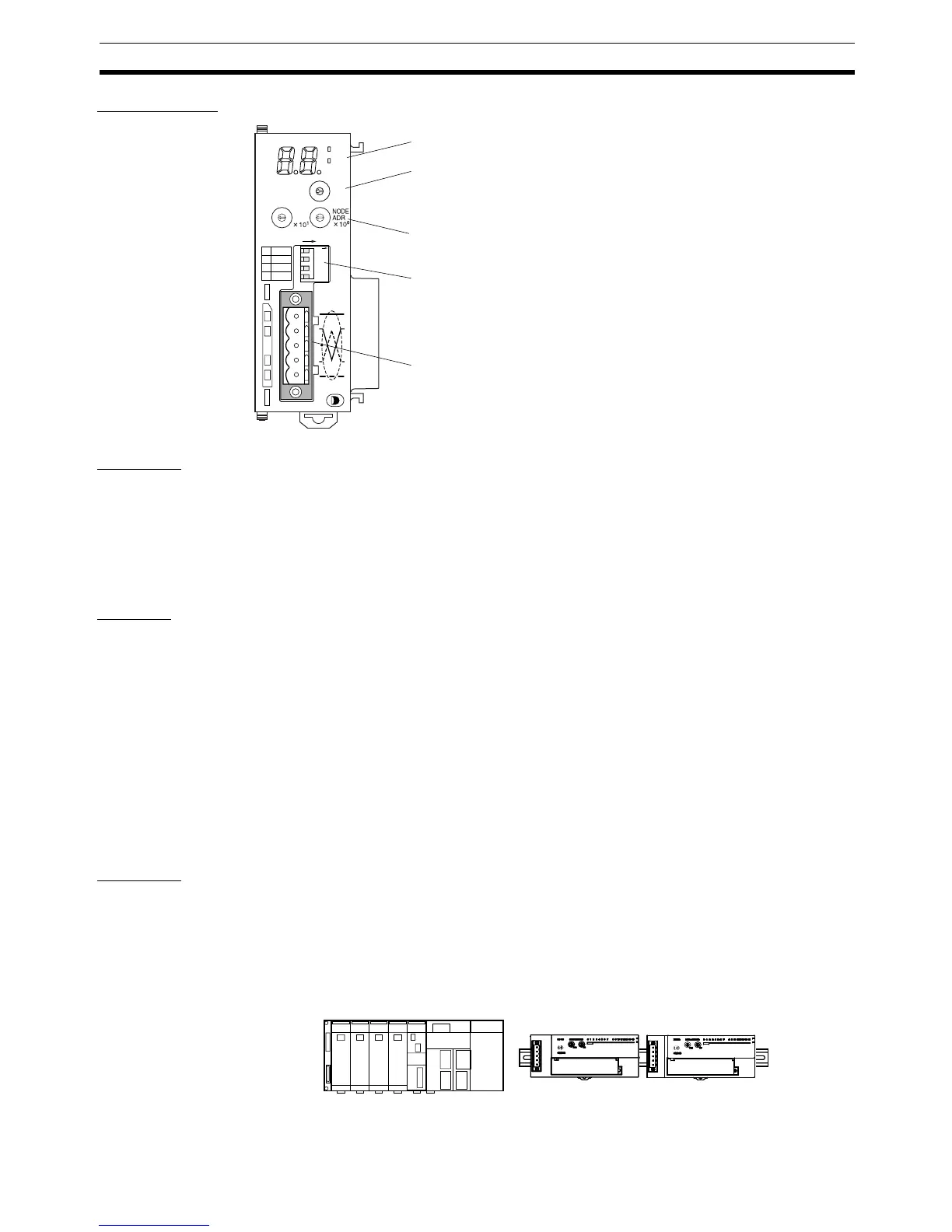
CJ1W-DRM21
Mounting The Master Unit is mounted to the Backplane of the PLC in the same way as
other Units are normally mounted. CJ-series Master Units have no Backplane,
so connect the Units together by joining the connectors. For details on mount-
ing Master Units to PLCs, and PLCs to control panels, refer to the applicable
PLC Operation Manual.
2-3-2 Mounting and Setting Slaves
Settings The following example shows Slave settings. For details on how to set Slaves,
refer to SECTION 5 General-purpose Slaves to SECTION 7 Analog Slaves.
• DRT2-ID16 Remote I/O Terminals (transistor inputs)
Node address: 01
• DRT2-OD16 Remote I/O Terminals (transistor outputs)
Node address: 02
• DRT2-ID16 Remote I/O Terminals (transistor inputs)
XWT-ID08 Remote I/O Terminal Expansion Unit
Node address: 03
• DRT2-OD16 Remote I/O Terminals (transistor outputs)
XWT-OD08 Remote I/O Terminal Expansion Unit
Node address: 04
Mounting Remote I/O Terminals are mounted by fixing to a DIN Track, as shown in the
following example.
Secure the bottom of the Slave Unit to a 35-mm DIN Track, or secure the
Slave Unit to the track between two End Plates.
Mounting Example The following diagram shows all Units except the PLC node mounted to DIN
Tra c k s.
1
1234
2
3
4
HOLD
ON
ESTP
DR1
DR0
DRM21
MS
NS
NO.
UNIT
0
1
2
3
4
5
6
7
8
9
A
B
C
D
E
F
0
1
2
3
4
5
6
7
8
9
0
1
2
3
4
5
6
7
8
9
ON
Indicators
Unit No. switch
This rotary switch sets the single-digit hexadecimal
unit number of the Master on the DeviceNet network.
Node address switches
These rotary switches set the double-digit decimal node address of the Unit.
DIP switches
These pins have the following functions:
Pins 1 and 2: Baud rate
Pins 3: Continue/stop remote I/O communications for error (for Master functions)
Pin 4: Hold/clear I/O for communications error (for Slave functions).
Communications connector
This connector is connected to the Network communications
cable. Communications power is also supplied through this
connector. An XW4B-05C1-H1-D Parallel Connector with
Screws is provided as the node connector.
0
Master
Remote I/O
Terminal (Input)
Remote I/O
Terminal (Output)

 Loading...


