225
Screw-less Clamp Terminals Section 5-7
Note 1. The I/O power supply’s right-side and left-side V terminals, and the right-
side and left-side G terminals, are not connected internally. Supply power
separately between V and G on the right and left sides respectively.
2. When using inductive loads (such as solenoid valves), use a load with a
built-in diode to absorb reverse power or attach a diode externally.
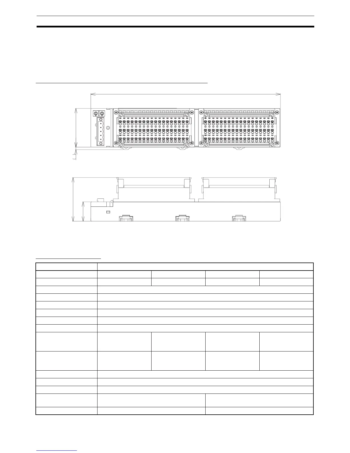
Dimensions (DRT2-OD32SL-1 and DRT2-OD32SLH-1)
5-7-8 Screw-less Clamp Terminals with 16 Transistor Inputs and
Outputs
Input Specifications
50
245
56.4
25
3
Item Specification
Model DRT2-MD32SL DRT2-MD32SL-1 DRT2-MD32SLH DRT2-MD32SLH-1
Internal I/O common NPN PNP NPN PNP
Input points 16 points
I/O power supply voltage 20.4 to 26.4 V DC (24 V DC, −15% to 10%)
Input current 6.0 mA max./point at 24 V DC, 3.0 mA min./point at 17 V DC
Input resistance 4 kΩ
ON delay time 1.5 ms max.
OFF delay time 1.5 ms max.
ON voltage 15 V DC min.
(between each input
terminal and V)
15 V DC min.
(between each input
terminal and G)
15 V DC min.
(between each input
terminal and V)
15 V DC min.
(between each input
terminal and G)
OFF voltage 5 V DC max.
(between each input
terminal and V)
5 V DC max.
(between each input
terminal and G)
5 V DC max.
(between each input
terminal and V)
5 V DC max.
(between each input
terminal and G)
ON current 3 mA min.
OFF current 1 mA max.
Number of circuits 16 points with one common
Power supply short-cir-
cuit protection
--- Operates at 50 mA/point min.
Disconnection detection --- Operates at 0.3 mA max.

 Loading...


