26
Setting and Wiring Hardware Section 2-3
2-3-3 Mounting Connecting Devices
The following connecting devices require being mounted:
• T-branch Taps: Secure to the control panel with screws, or mount to a DIN
Tra c k .
• Terminal-block Terminating Resistors: Secure to the control panel with
screws.
2-3-4 Connecting Cables
Connecting
Communications
Cables
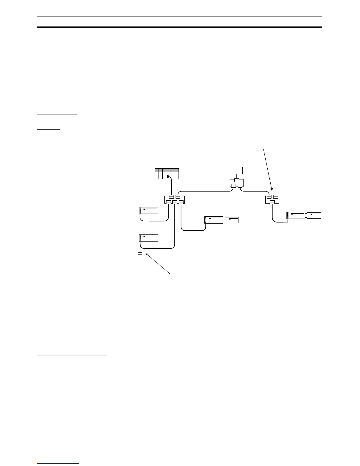
Connect the Master Unit and T-branch Taps, T-branch Taps and T-branch
Taps, and T-branch Taps and Slaves using Thin DeviceNet Communications
Cables, as shown in the following diagram.
Use the following procedure to connect the cables. Refer to 5-2 Connecting
Communications Cables to General-purpose Slaves for details.
1,2,3... 1. Prepare the communications cables and attach the connectors to the ca-
bles.
2. Connect the communications cable connectors to the node connectors on
the Master Unit, T-branch Taps, and Slaves.
Wiring the I/O Power
Supply
If required, an I/O power supply for I/O devices is connected to the Remote
I/O Terminals. Connect M3 crimp terminals to the power lines and then con-
nect them to the terminal block.
Wiring I/O Wire the I/O to the Remote I/O Terminals.
Connect M3 crimp terminals to the signal lines and then connect them to the
terminal block.
When a Terminating Resistor is required, connect it to the
final T-branch Tap in the Network. The T-branch Tap must
be no further than 6 m from the final node.
CS Rack
Remote I/O
Terminal
Terminating
Resistor
If a Terminal-block Terminating Resistor is required, connect it to
the end of an extension cable (1 m max.) that is connected to the
final node.
24-V DC power
supply
T-branch
Tap
T-branch
Tap
T-branch
Tap
Remote I/O
Terminal
Remote I/O
Terminal
Remote I/O
Terminal

 Loading...


