359
Analog Output Terminals Section 7-5
Calculation Example When using three points, and applying scaling to the first and second inputs,
and the cumulative counter to the third input, the maximum AD conversion
cycle time can be obtained by using the following formula.
Formula: 3.21 + (0.055 x 2) + 0.035 = 3.355 ms
Note With the DRT2-DA04H, the conversion cycle time is within 250 ms even when
all of the math operations are being used.
7-5 Analog Output Terminals
7-5-1 DRT2-DA02 Analog Output Terminal
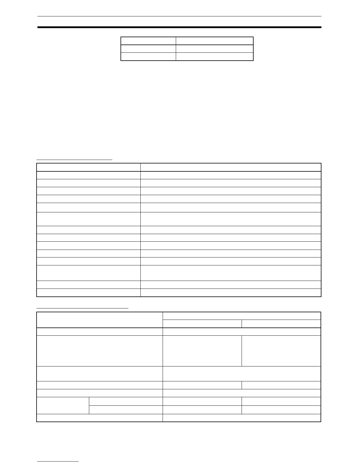
General Specifications
Performance Specifications
Rate of change 0.030
Cumulative counter 0.035
Math operation Additional time for each point
Item Specifications
Communications power supply voltage 11 to 25 V DC (Supplied from the communications connector.)
Current consumption 120 mA max. (24 V DC)
Noise immunity Conforms to IEC61000-4-4. 2 kV (power lines)
Vibration resistance 10 to 150 Hz, 0.7-mm double amplitude
Shock resistance
150 m/s
2
Dielectric strength 500 V AC for 1 min. with 1-mA sensing current (between communications
and analog circuits)
Ambient temperature –10 to +55°C
Ambient humidity 25% to 85% (with no condensation)
Operating environment No corrosive gases
Storage temperature –25 to +65°C
Mounting 35-mm DIN Track mounting
Mounting strength 50 N
In the direction of the Track: 10 N
Screw tightening torque M3 (power supply, I/O terminals): 0.5 N·m
Weight 150 g max.
Item Specifications
Voltage output Current output
Output points 2 points (outputs 0 and 1)
Output type 0 to 5 V
1 to 5 V
0 to 10 V
–10 to 10 V
0 to 20 mA
4 to 20 mA
Output range setting method • DIP switch: Outputs 0 and 1 set separately.
• Configurator: Outputs 0 and 1 set separately.
External output allowable load resistance 1 kΩ min. 600 Ω max.
Resolution 1/6,000 (full scale)
Overall accuracy 25°C
±0.4% FS ±0.4% FS
–10 to 55°C
±0.8% FS ±0.8% FS
Conversion time 2 ms/ 2 points

 Loading...


