160
Connector Terminals with Transistors Section 5-6
external loads exceeds 2 A, the output power supply should not be input
through the terminals; an external power supply must be used instead.
2. When using inductive loads (such as solenoid valves), use a load with a
built-in diode to absorb reverse power or attach a diode externally.
I/O Allocations The first word allocated to the Remote Input Terminal is referred to as “word
m.” Given this, the bit and word allocations to MIL connector pin numbers are
as shown in the following diagram.
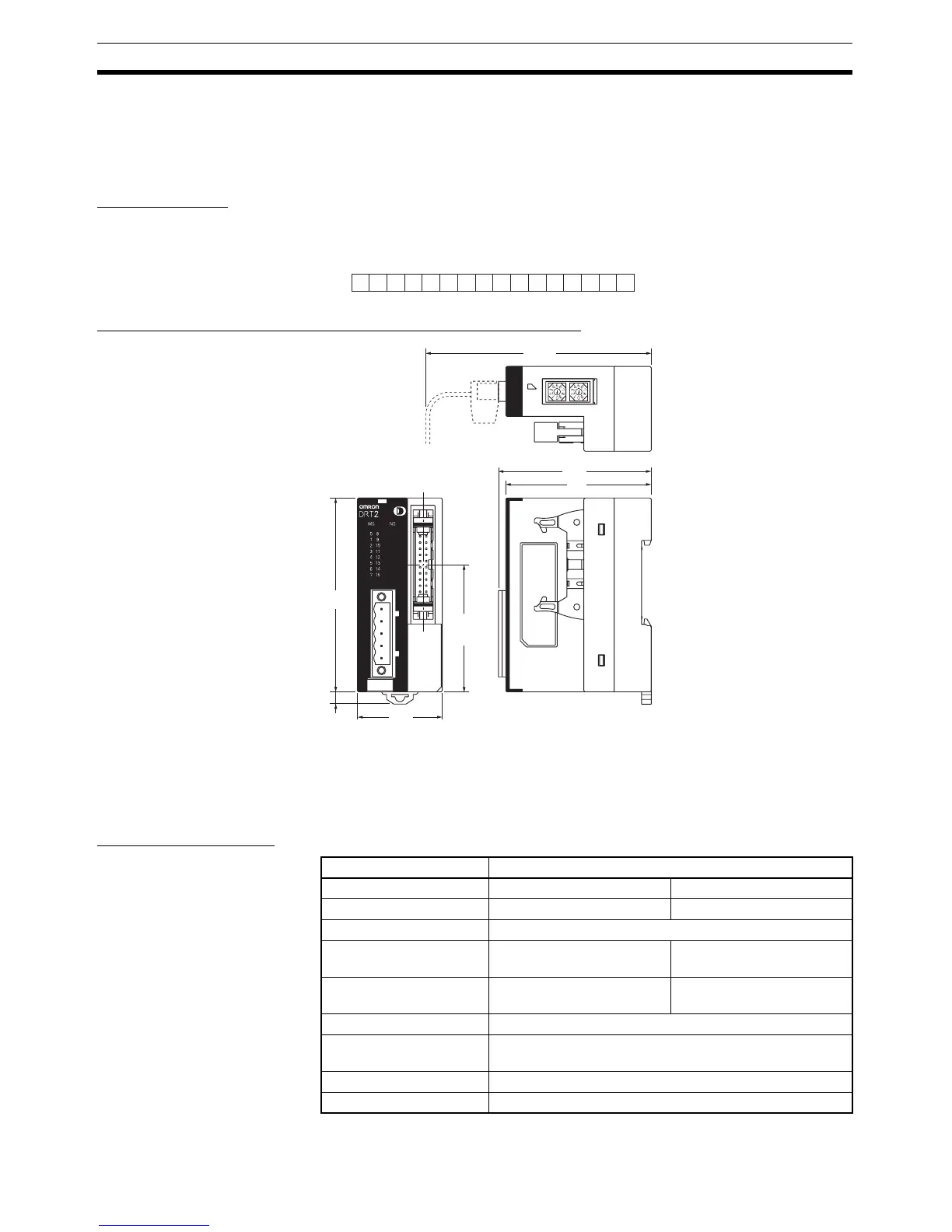
Dimensions (DRT2-OD16ML(X) and DRT2-ID16ML(X)-1)
5-6-7 Transistor Remote Input Terminals with 32 Points and
Connectors: DRT2-ID32ML (NPN) and DRT2-ID32ML-1 (PNP)
Input Specifications
1514131211109876543210
5
Wd m
7 9 11 13 15 17 19 6 8 10 12 14 16 18 20
Bit
16 output
Values in parentheses are
reference values.
80
5
52.7
35
(83)
63
60
Item Specification
Model DRT2-ID32ML DRT2-ID32ML-1
Internal I/O common NPN PNP
Input points 32 points
ON voltage 17 V DC min. (between
each input terminal and V)
17 V DC min. (between
each input terminal and G)
OFF voltage 5 V DC max. (between
each input terminal and V)
5 V DC max. (between
each input terminal and G)
OFF current 1.0 mA max.
Input current 6.0 mA max./point at 24 V DC
3.0 mA min./point at 17 V DC
ON delay time 1.5 ms max.
OFF delay time 1.5 ms max.

 Loading...


