161
Connector Terminals with Transistors Section 5-6
Note All 32 inputs can be ON simultaneously if the Remote I/O Terminal is mounted
facing up, but sufficient space will need to be allowed between Units depend-
ing on the ambient temperature. Refer to the Dimensions diagram on
page 165 for details.
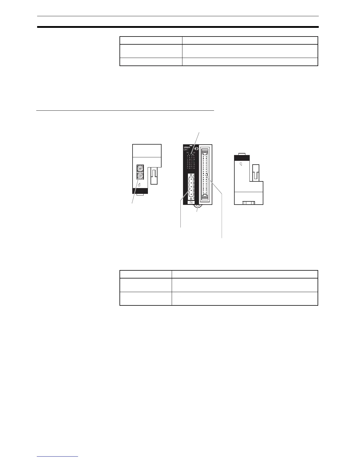
Components of the DRT2-ID32ML and DRT2-ID32ML-1
Input Indicators
Note “m” is the first word allocated to the Remote Input Terminal.
Max. simultaneously ON
input points
32 points (See note.)
Number of circuits 32 points with one common
Item Specification
(×10)
(×1)
2
Top panel Front panel Bottom panel
DeviceNet indicators
Indicate the status of the Slave, communications,
and inputs (lit when input is ON).
Rotary switches
Set the node address.
DIN track
mounting hooks
Communications
connector
Input connector (MIL)
Connects the 32 inputs via a MIL connector.
The MIL cable is sold separately.
Name Meaning
I0 to I15 Indicate the status of bits (contacts) 0 to 15 in word m. Lit
when input is ON; not lit when input is OFF.
II0 to II15 Indicate the status of bits (contacts) 0 to 15 in word m+1. Lit
when input is ON; not lit when input is OFF.

 Loading...


