142
Remote I/O Terminals with Transistors Section 5-5
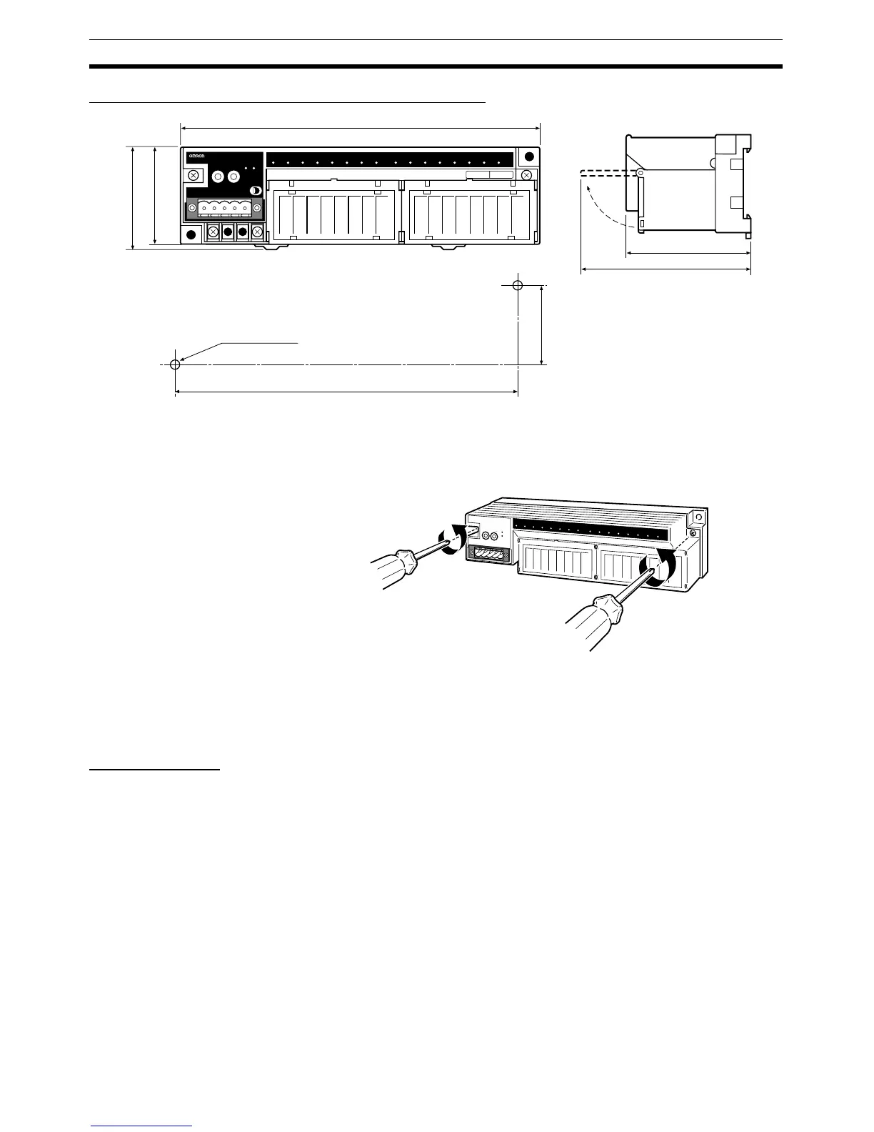
Dimensions: DRT2-MD16TA and DRT2-MD16TA-1
Note The circuit section can be removed by loosening the circuit removal screws.
(Refer to Components of the DRT2-MD16TA and DRT2-MD16TA-1.)
Always turn OFF the communications, internal, and I/O power supplies before
removing or attaching the circuit section.
5-5-16 Mounting in Control Panels
A Remote I/O Terminal (Basic Unit or Expansion Unit) can be mounted in a
control panel using either of the following methods.
Using DIN Track Mount the back of the Remote I/O Terminal to a 35-mm DIN Track. To mount
the Terminal, pull down on the mounting hook on the back of the Terminal with
a screwdriver, latch the DIN Track onto the back of the Terminal, and then
secure the Terminal to the DIN Track. Secure all Slaves on both ends of the
DIN Track with End Plates.
Connecting End Plates Hook the bottom of the End Plate onto the DIN Track, as shown at (1) in the
following diagram, then hook the top of the End Plate as shown at (2).
170±0.2
40±0.2
58
(83)
180
50
(54)
Two, 4.2 dia. or M4
Mounting holes
Values in parentheses are
reference values.
DRT2-MD16TA
REMOTE TERMINAL DC24V
NS
MS
IN OUT

 Loading...


