286
Mounting and Wiring Environment-resistive Slaves Section 6-6
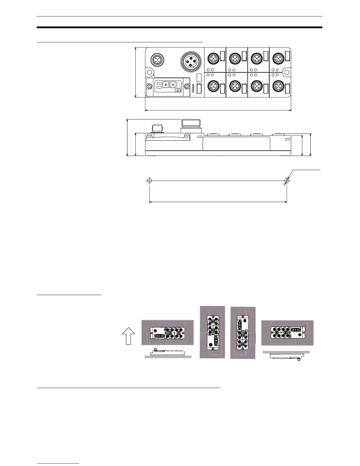
Dimensions: DRT2-MD16CL and DRT2-MD16CL-1
6-6 Mounting and Wiring Environment-resistive Slaves
6-6-1 Mounting in Control Panels
Use screws to mount the Environment-resistive Terminal in the Control Panel.
Environment-resistive Terminals cannot be mounted on a DIN Track.
Drill the mounting holes in the control panel according to the dimensions
shown in the dimensions diagrams and secure the Terminal with M5 screws.
The appropriate tightening torque is 1.47 to 1.96 N·m.
Mounting Direction The terminal can be mounted in any of the following six directions.
6-6-2 Wiring the Internal Power Supply, I/O Power Supply, and I/O Lines
Wiring the Internal Power Supply and I/O Power Supply
DRT2-ID08C(-1) and
DRT2-HD16C(-1)
The internal power supply and I/O power supply share the communications
power supply so an external power supply is not required.
3
1
5
4
2
4
4
5
1
4
3
2
4
2
2
3
5
41
5
1
8
4
5
3
7
B
A
B
A
B
A
B
A
B
A
B
A
B
A
A
B
2
1
3
1
3
3
2
2
2
5
4
5
1
2
4
3
5
5
1
1
6
3
5
4
3
2
1
0
9
8
7
6
5
4
3
2
1
0
9
8
7
6
NOD
ADR
X 10
X 1
OUT PWR
IN PWR
60
175
Two 5.3 dia. or M5
mounting holes
43.9
27.3
165±0.2
24.3
26.6
Mounting hole dimensions
Ver tical

 Loading...


