308
Common Procedures Section 7-2
7-2 Common Procedures
7-2-1 Connecting Communications Cables
Communications cables are connected using the same methods as for Gen-
eral-purpose Slaves. Refer to 5-2 Connecting Communications Cables to
General-purpose Slaves for details.
7-2-2 Node Address and Baud Rate Settings
The Analog Slaves' node address and baud rate settings are described here.
Node address setting: Use rotary switch or the Configurator
Baud rate setting: Automatically detected from the Master
Node Address
Settings
The node address of the Analog Slave is set as a decimal value using the left
rotary switch for the ten's digit and the right rotary switch for the one's digit.
(Up to 63 nodes can be set.)
Node addresses 64 to 99 can be set using the Configurator using the follow-
ing method.
Note The rotary switch settings are read when the power is turned ON.
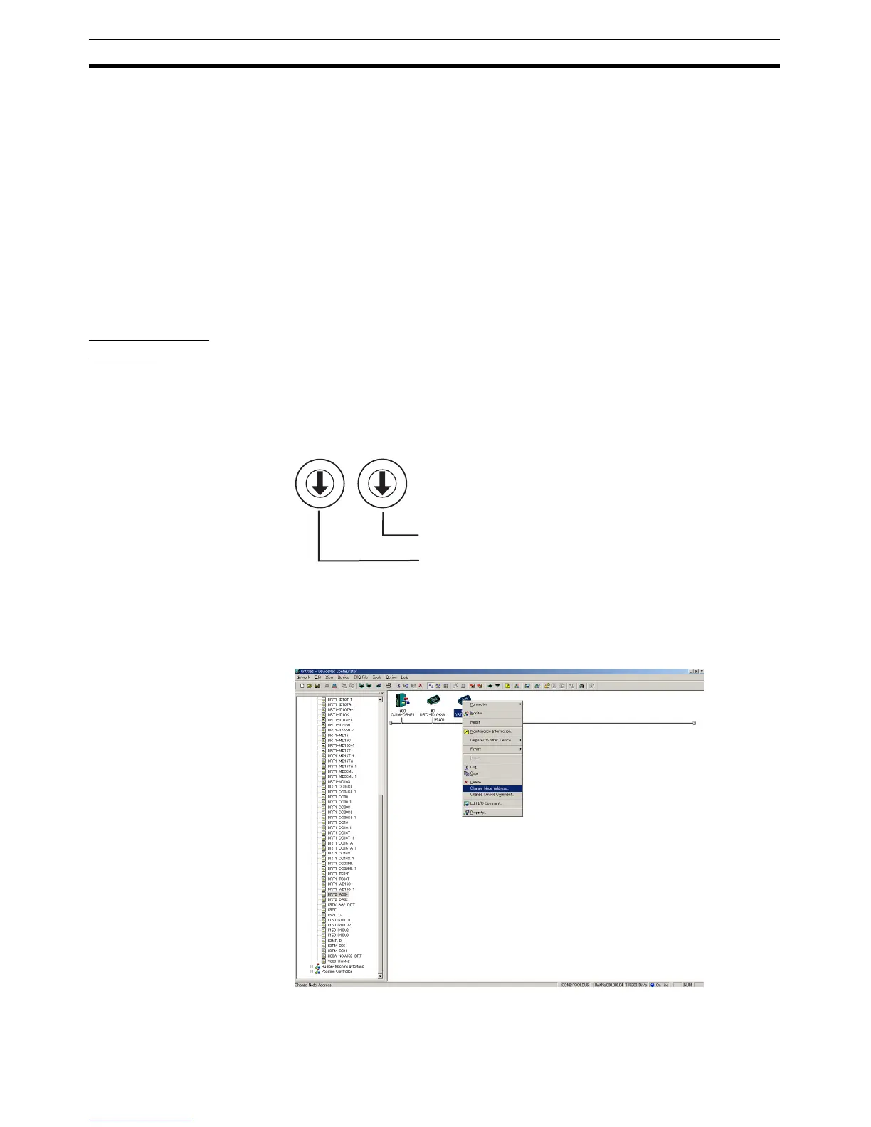
Setting Node Addresses Using the DeviceNet Configurator
1,2,3... 1. Click the right mouse button over the icon of the corresponding DRT2 An-
alog Slave in the Network Configuration Window, and select Change
Node Address.
0
1
2
3
4
5
6
7
8
9
0
1
2
3
4
5
6
7
8
9
Node address, x1
Node address, x10

 Loading...


