119
Remote I/O Terminals with Transistors Section 5-5
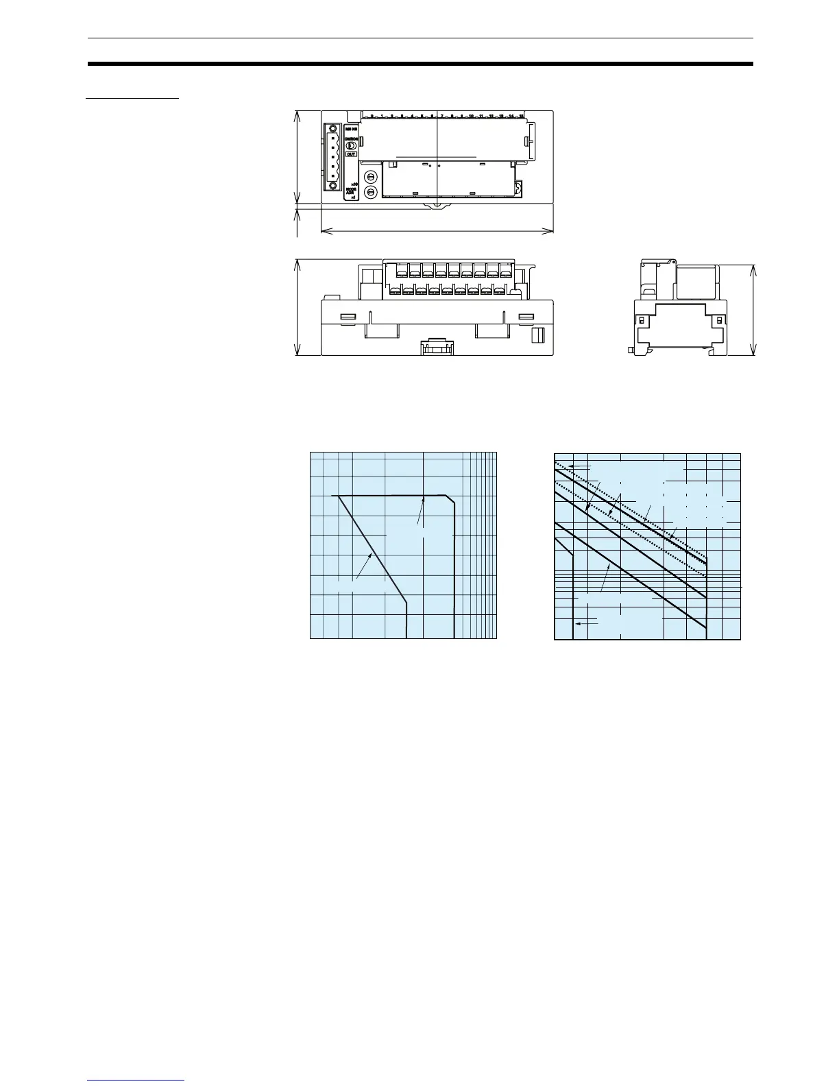
Dimensions
Reference Data The data shown below is based on actual measurements of samples taken
from the production line. There is some degree of variation in relay character-
istics and so this data should be used only for reference purposes.
Note 1. With a current of between 2 and 3 A (common: 8 to 10 A), either ensure
that the number of points per common that simultaneously turn ON does
not exceed 4 or ensure that the temperature does not exceed 45
°C. There
are no restrictions if the current does not exceed 2 A (common: 8 A).
2. Using at the rated current value assures normal Unit operation but does
not assure the life expectancy of the relay itself. The relay’s life expectancy
varies greatly with the operating temperature, type of load, and switching
conditions, and so be sure to check the relay characteristics under the ac-
tual operating conditions.
50
3.1
125
51.8
48.8
0.1
0.3
0.5
1
3
5
2
3
5
10
20
30
50
100
200
300
500
0.1
0.3
0.5
1
3
5
10
20
200
500
1000
30
30050
100
0.2
2
0.2
4
0.4
4
Life expectancy (
×
10
4
times)
Life Expectancy Curve
Switching current (A)
Maximum Switching Capacity
AC resistive load
30 VDC, t = 40 ms
30-VDC/240-VAC
resistive load
240 VAC, COSφ = 0.4
Switching current (A)
DC resistive load
Switching voltage (V)
100 to 200 VDC
t = 7 to 40 ms
120-VAC resistive load
120 VAC, COSφ = 0.4
30 VDC, t = 7 ms

 Loading...


