138
Remote I/O Terminals with Transistors Section 5-5
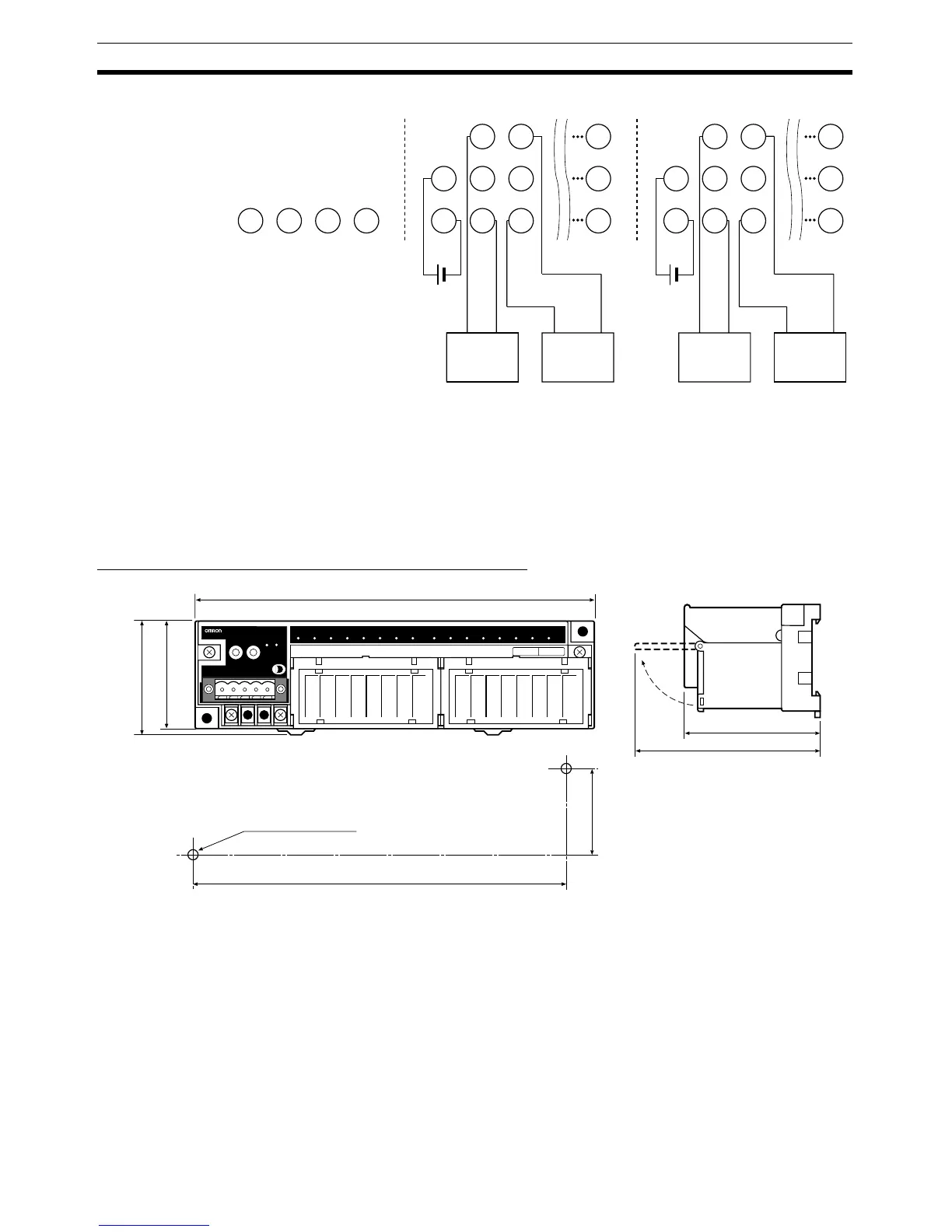
DRT2-OD16TA-1 (PNP)
Note 1. V1 is not connected internally to V2, and G1 is not connected internally to
G2. Connect them carefully.
2. When using inductive loads (such as solenoid valves), use a load with a
built-in diode to absorb reverse power or attach a diode externally.
3. Do not connect anything to the reserved terminals.
Dimensions: DRT2-OD16TA and DRT2-OD16TA-1
Note The circuit section can be removed by loosening the circuit removal screws.
(Refer to Components of the DRT2-OD16TA and DRT2-OD16TA-1.)
7
V1
G1
1
V1
G1
0
V1
G1
V1
G1
−+
15
V2
G2
9
V2
G2
8
V2
G2
V2
G2
−+
Solenoid
valve, etc.
Solenoid
valve, etc.
Solenoid
valve, etc.
Solenoid
valve, etc.
170±0.2
40±0.2
58
(83)
180
50
(54)
Two, 4.2 dia. or M4
Mounting holes
Values in parentheses are
reference values.
DRT2-OD16TA
REMOTE TERMINAL DC24V
NS
MS
OUT

 Loading...


