147
Connector Terminals with Transistors Section 5-6
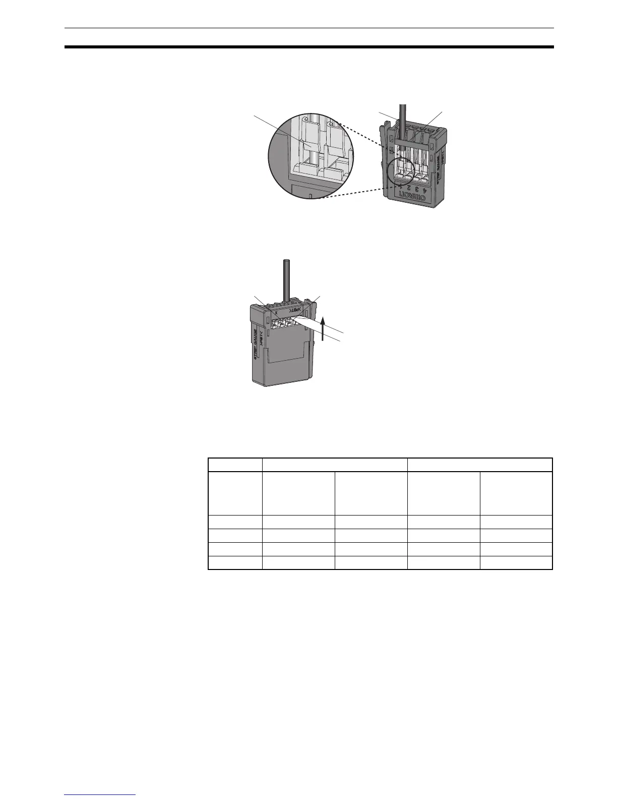
2. Insert the line all the way to the back of the wire insertion opening. Check
that the sheath of the line is inserted into the wire insertion opening, and
that the end of the conductor has passed through the connection part.
3. Insert a flat-blade screwdriver into the reset opening and pull back the lever
lightly. A click sound will be heard and the operation lever will return to its
normal position.
4. Check that the operation lever has returned to its position. Lightly pull on
the lines, and if there is any resistance, they are connected properly.
Note When connecting the sensor, insert the wire so that the terminal number on
the cover matches the sensor wire color, as shown in the following table.
Note Wire colors have been changed according to revisions in the JIS
standards for photoelectric and proximity sensors. The colors in pa-
rentheses are the wire colors prior to the revisions.
Note To remove a wire, push in the operation lever, check that the operation lever
has locked, and then pull out the wire. After removing the wire, always return
the operation lever to its normal position.
Wire insertion opening
Wire sheath
Connection part
Reset opening
Operation lever
(white)
Using DRT2-ID16S Using DRT2-ID16S-1
Ter minal
number
3-wire sensor
(without self-
diagnostic out-
put function)
2-wire sensor
(without self-
diagnostic out-
put function)
3-wire sensor
(without self-
diagnostic out-
put function)
2-wire sensor
(without self-
diagnostic out-
put function)
1 Brown (red) --- Brown (red) Brown (white)
2 --- --- --- ---
3 Blue (black) Blue (black) Blue (black) ---
4 Black (white) Brown (white) Black (white) Blue (black)

 Loading...


