152
Connector Terminals with Transistors Section 5-6
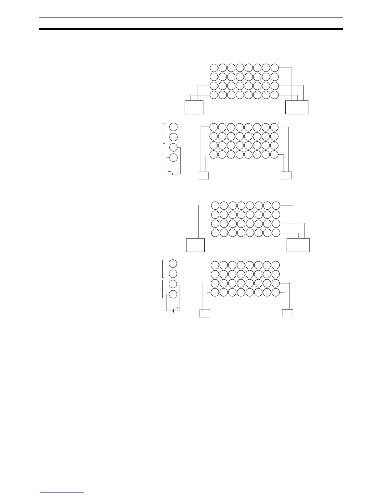
Wiring
DRT2-MD16S (NPN)
DRT2-MD16S-1 (PNP)
Note 1. There are two V0 terminals and two G0 terminals for I/O power supply ter-
minals in the output section. Use one pair of these terminals for the I/O
power supply for this Unit and the other pair for the I/O power supply for the
next Unit. Do not exceed 3 A for either pair.
2. Wire colors in parentheses are the previous JIS colors for photoelectric
and proximity sensors.
V1
NC
G1
IN
0
V1
NC
IN
1
V1
NC
IN
2
V1
NC
IN
3
V1
NC
IN
4
V1
NC
IN
5
V1
NC
IN
6
V1
NC
IN
7
V2
NC
NC
OUT
0
1
2
NC
NC
OUT
1
NC
NC
OUT
2
NC
NC
OUT
3
NC
NC
OUT
4
NC
NC
OUT
5
NC
NC
OUT
6
NC
NC
OUT
7
3
4
1
2
3
4
G1
G2 G2
G3
G3 G4
G4
V2
V2
V2
V2
V2 V2
V2
Blue
(black)
Brown
(white)
2-wire sensor
(e.g., limit switch)
Blue
(black)
Black
(white)
Brown
(red)
3-wire sensor with NPN output
(photoelectric or proximity sensor)
Solenoid
valve, etc.
Solenoid
valve, etc.
G0
G0
V0
V0
You can connect
either V0 terminal.
You can connect
either G0 terminal.
V1
NC
G1
IN
0
V1
NC
IN
1
V2
NC
IN
2
V2
NC
IN
3
V3
NC
IN
4
V3
NC
IN
5
V4
NC
IN
6
V4
NC
IN
7
NC
NC
G2
OUT
0
1
2
NC
G2
OUT
1
NC
G2
OUT
2
NC
G2
OUT
3
NC
G2
OUT
4
NC
G2
OUT
5
NC
G2
OUT
6
NC
G2
OUT
7
3
4
1
2
3
4
G1
G1 G1
G1
G1 G1
G1
NC
NC
NC
NC
NC NC
NC
Blue
(black)
Brown
(white)
2-wire sensor
(e.g., limit switch)
Blue
(black)
Black
(white)
Brown
(red)
3-wire sensor with PNP output
(photoelectric or proximity sensor)
Solenoid
valve, etc.
Solenoid
valve, etc.
G0
G0
V0
V0
You can connect
either V0 terminal.
You can connect
either G0 terminal.

 Loading...


