156
Connector Terminals with Transistors Section 5-6
2. Wire the V terminals and G terminals correctly so that the following func-
tions operate properly.
• I/O Power Status Monitor
• Contact Operation Counter
• Total ON Time Monitor
• Function preventing malfunction caused by inrush current at startup.
If these functions are not being used, input signals will be received even if
the G terminals of the DRT2-ID16ML(X) or V terminals of the DRT2-
ID16ML(X)-1 are not connected.
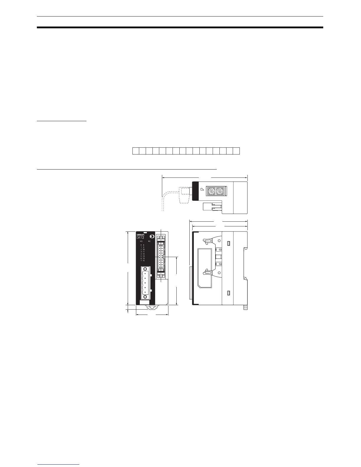
I/O Allocations The first word allocated to the Remote Input Terminal is referred to as “word
m.” Given this, the bit and word allocations to MIL connector pin numbers are
as shown in the following diagram.
Dimensions (DRT2-ID16ML(X) and DRT2-ID16ML(X)-1)
Note There are restriction when using the 16-point Transistor Remote Input Termi-
nals with Connectors depending on the ambient operating temperature.
• If the Terminals are not mounted facing up, they can be mounted side-by-
side and all inputs can be turned ON simultaneously at 55
°C or less.
• If the Terminals are mounted facing up, the distances and temperatures in
the graph given below must be maintained to enable turning ON all inputs
15 14 13 12 11 10 9 8 7 6 5 4 3 2 1 0
5
Wd m
7 9 11 13 15 17 19 6 8 10 12 14 16 18 20
Bit
16 inputs
60
63
(83)
35
80
52.7
5
Values in parentheses are
reference values.

 Loading...


