158
Connector Terminals with Transistors Section 5-6
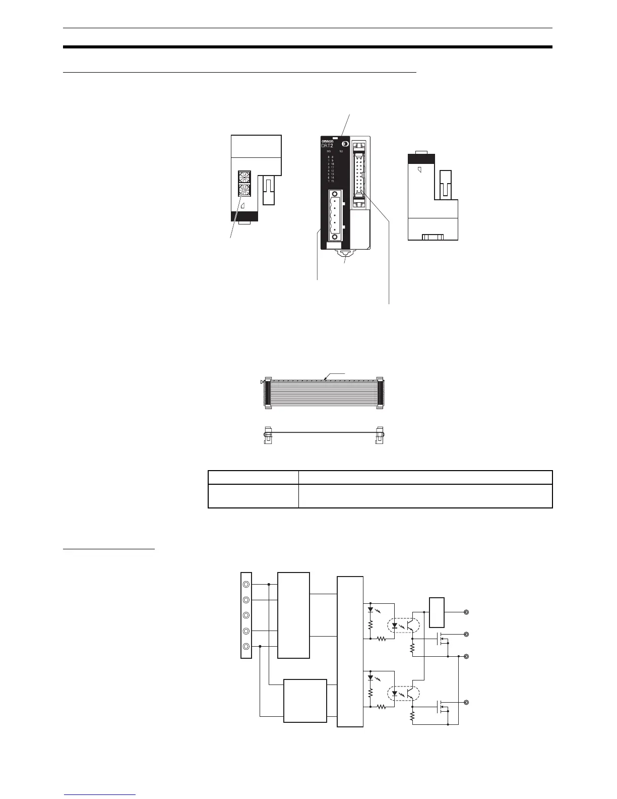
Components of the DRT2-OD16ML(X) and DRT2-OD16ML(X)-1
Output Indicators
Note “m” is the first word allocated to the Remote Output Terminal.
Internal Circuits
DRT2-OD16ML(X) (NPN)
Top panel Front panel Bottom panel
DeviceNet indicators and Output Indicators
Indicate the status of the Slave, communications,
and each output (lit when output is ON).
Rotary switches
Set the node address.
DIN track
mounting hooks
Communications
connector
Output connector (MIL)
Connects the 16 outputs via a MIL connector.
A cable (10 cm) with only an MLX connector
is included.
(×10)
(×1)
T 20
Connectors with Cable (MLX Models Only)
Green
Name Meaning
I0 to I15 Indicate the status of bits (contacts) 0 to 15 in word m. Lit
when output is ON; not lit when output is OFF.
V1
G
V+
CAN_H
DRAIN
CAN_L
V−
Internal
circuitry
Output (0 to 7)
Output (8 to 15)
Physical
layer
DC-DC
converter
(non-
isolated)
Photo-
coupler
Photo-
coupler
Voltage
step-down

 Loading...


