169
Connector Terminals with Transistors Section 5-6
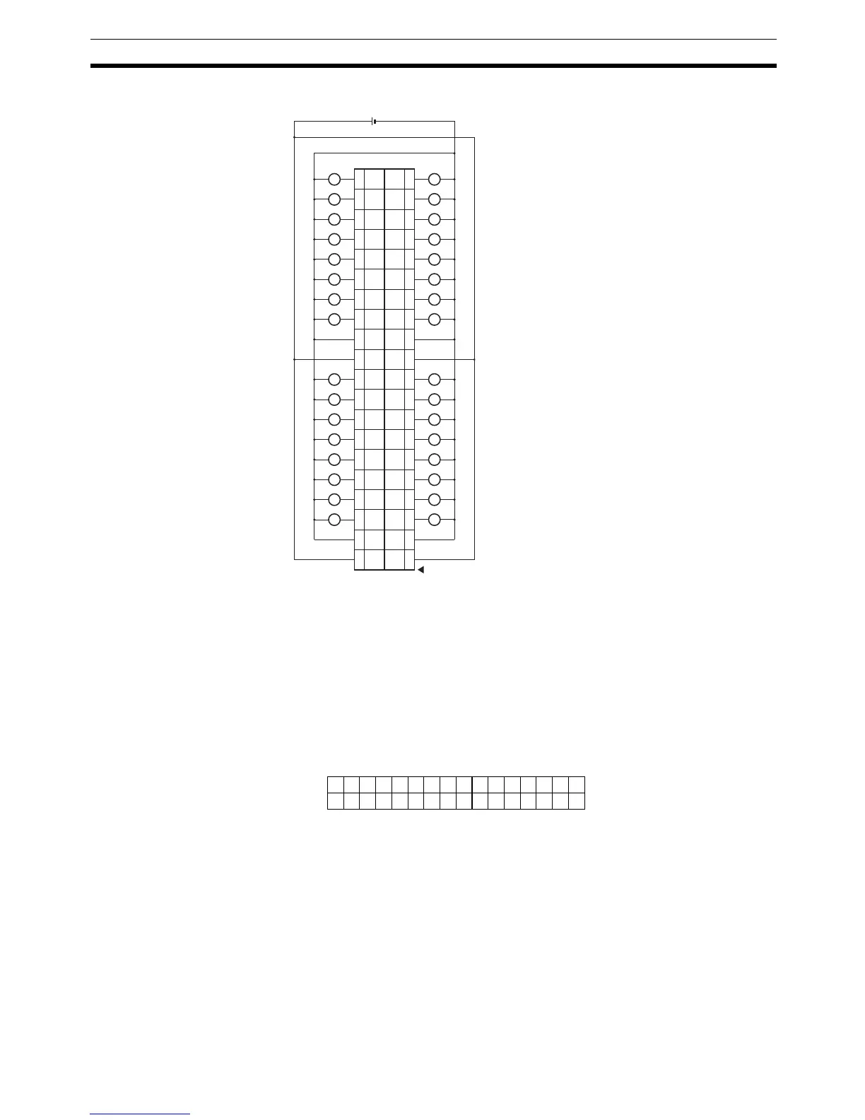
DRT2-OD32ML-1 (PNP)
Note 1. The V terminals are connected internally, as are the G terminals. When the
power supply exceeds 1.0 A per terminal or the total current drawn by the
external loads exceeds 4 A, the output power supply should not be input
through the terminals; an external power supply must be used instead.
2. When using inductive loads (such as solenoid valves), use a load with a
built-in diode to absorb reverse power or attach a diode externally.
I/O Allocations The first word allocated to the Remote Output Terminal is referred to as “word
m.” Given this, the bit and word allocations to MIL connector pin numbers are
as shown in the following diagram.
L
L
L
L
L
L
L
L
L
L
L
L
L
L
L
L
L
L
L
L
L
L
L
L
L
L
L
L
L
L
L
L
24 V DC
40
VV
39
38
GG
37
36 35
34
Wd
m+1
09
Wd
m+1
01
Wd
m+1
08
Wd
m+1
00
33
32
Wd
m+1
02
Wd
m+1
10
31
30
Wd
m+1
03
Wd
m+1
11
29
28
Wd
m+1
04
Wd
m+1
12
27
26
Wd
m+1
05
Wd
m+1
13
25
24
Wd
m+1
06
Wd
m+1
14
23
22
Wd
m+1
07
Wd
m+1
15
21
20
VV
19
18
GG
17
16 15
14
Wd m
01
Wd m
09
Wd m
00
Wd m
08
13
12
Wd m
02
Wd m
10
11
10
Wd m
03
Wd m
11
9
8
Wd m
04
Wd m
12
7
6
Wd m
05
Wd m
13
5
4
Wd m
06
Wd m
14
3
2
Wd m
07
Wd m
15
1
15 14 13 12 11 10 9 8 7 6 5 4 3 2 1 0
25 27 29 31 33 35 37 39 26 28 30 32 34 36 38 40
5
Wd m
Wd m+1 7 9 11 13 15 17 19 6 8 10 12 14 16 18 20
Bit
16 outputs
16 outputs

 Loading...


