174
Connector Terminals with Transistors Section 5-6
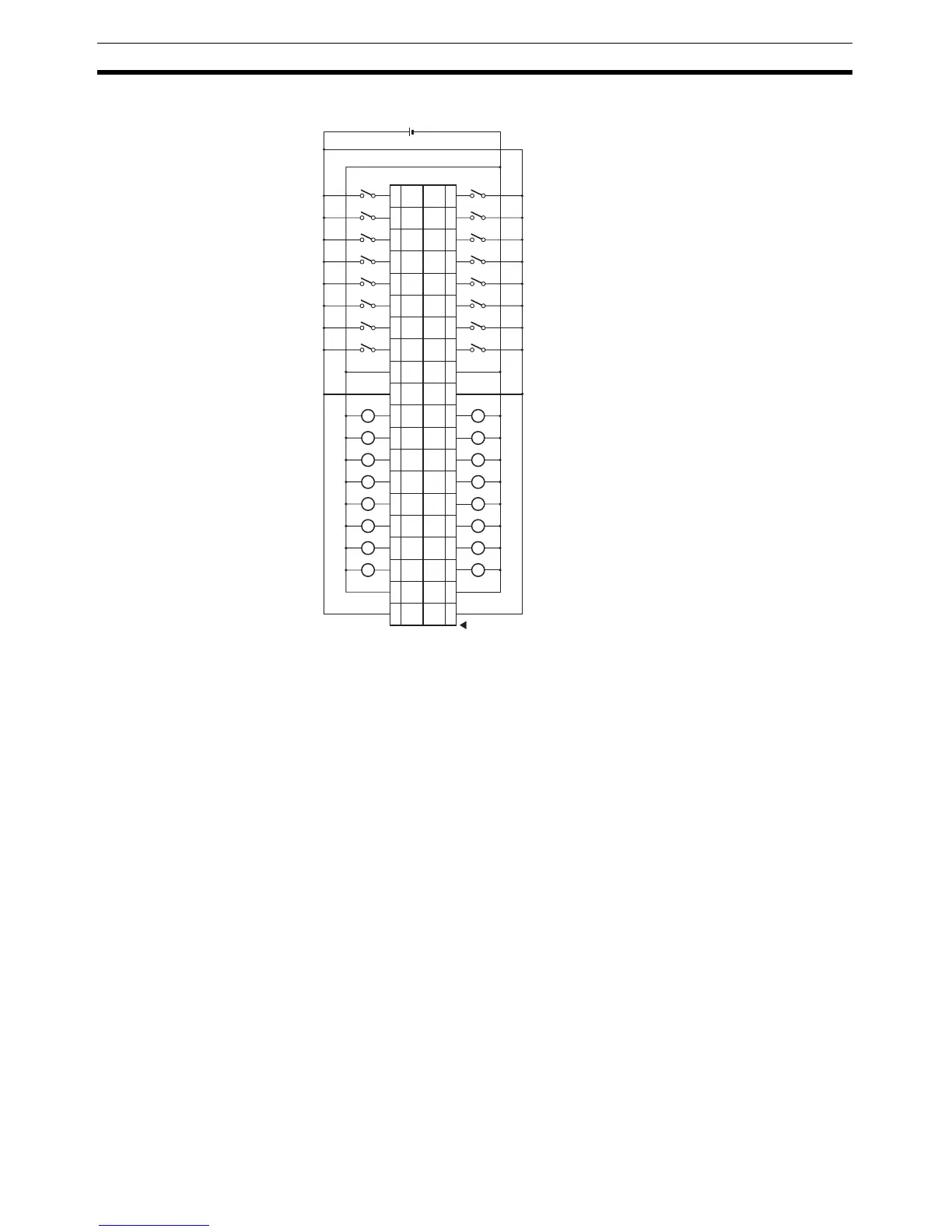
DRT2-MD32ML-1 (PNP)
Note 1. The V1 terminals are connected internally, as are the V2 terminals, the G1,
and the G2 terminals. (V1 is not connected to V2 and G1 is not connected
to G2.) When the power supply exceeds 1.0 A per terminal or the total cur-
rent drawn by the external loads exceeds 2 A, the output power supply
should not be input through the terminals; an external power supply must
be used instead.
2. When using inductive loads (such as solenoid valves), use a load with a
built-in diode to absorb reverse power or attach a diode externally.
3. Wire the V1 terminals and G1 terminals correctly so that the following func-
tions operate properly.
• I/O Power Status Monitor
• Contact Operation Counter
• Total ON Time Monitor
• Function preventing malfunction caused by inrush current at startup.
If these functions are not being used, input signals will be received even if
the G1 terminals of the DRT2-ID32ML or V1 terminals of the DRT2-
ID32ML-1 are not connected.
L
L
L
L
L
L
L
L
L
L
L
L
L
L
L
L
24 V DC
40
G1 G1
39
38
V1 V1
37
36 35
34 33
32 31
30 29
28 27
26 25
24 23
22 21
20 19
18 17
16 15
14 13
12 11
10 9
87
65
43
21
G2 G2
V2 V2
OUT
01
OUT
09
OUT
00
OUT
08
OUT
02
OUT
10
OUT
03
OUT
11
OUT
04
OUT
12
OUT
05
OUT
13
OUT
06
OUT
14
OUT
07
OUT
15
IN
01
IN
09
IN
00
IN
08
IN
02
IN
10
IN
03
IN
11
IN
04
IN
12
IN
05
IN
13
IN
06
IN
14
IN
07
IN
15

 Loading...


