187
Connector Terminals with Transistors Section 5-6
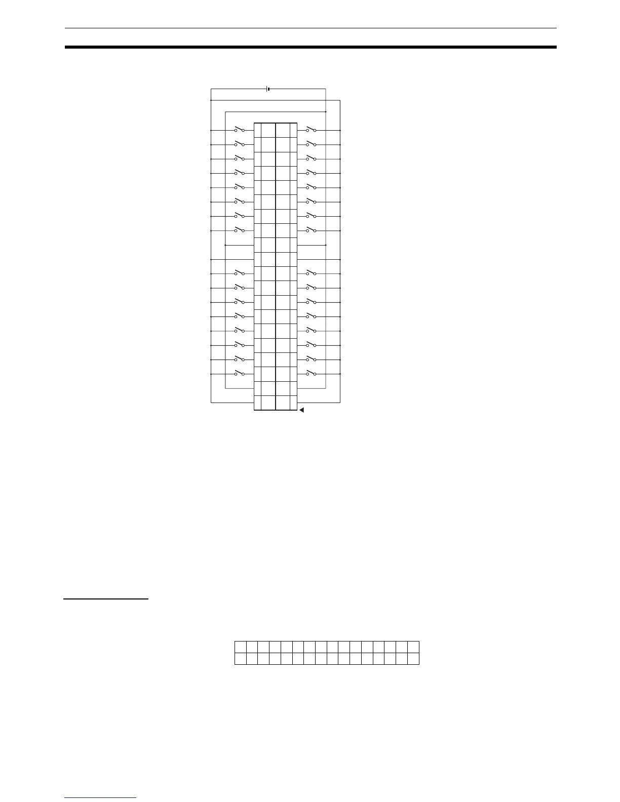
DRT2-ID32B-1 and DRT2-ID32BV-1 (PNP)
Note 1. V terminals are connected internally, as are the G terminals. Connect them
carefully.
2. Wire the V terminals and G terminals correctly so that the following func-
tions operate properly.
• I/O Power Status Monitor
• Contact Operation Counter
• Total ON Time Monitor
• Function preventing malfunction caused by inrush current at startup.
If these functions are not being used, input signals will be received even if
the G terminals of the DRT2-ID32B and DRT2-ID32BV or V terminals of
the DRT2-ID32B-1 and DRT2-ID32BV-1 are not connected.
I/O Allocations The first word allocated to the Remote I/O Terminal is referred to as “word m.”
Given this, the bit and word allocations to MIL connector pin numbers are as
shown in the following diagram.
24 V DC
40
VV
39
38
GG
37
36 35
34
Wd
m+1
09
Wd
m+1
01
Wd
m+1
08
Wd
m+1
00
33
32
Wd
m+1
02
Wd
m+1
10
31
30
Wd
m+1
03
Wd
m+1
11
29
28
Wd
m+1
04
Wd
m+1
12
27
26
Wd
m+1
05
Wd
m+1
13
25
24
Wd
m+1
06
Wd
m+1
14
23
22
Wd
m+1
07
Wd
m+1
15
21
20
VV
19
18
GG
17
16 15
14
Wd m
01
Wd m
09
Wd m
00
Wd m
08
13
12
Wd m
02
Wd m
10
11
10
Wd m
03
Wd m
11
9
8
Wd m
04
Wd m
12
7
6
Wd m
05
Wd m
13
5
4
Wd m
06
Wd m
14
3
2
Wd m
07
Wd m
15
1
15 14 13 12 11 10 9 8 7 6 5 4 3 2 1 0
25 27 29 31 33 35 37 39 26 28 30 32 34 36 38 40
5
Wd m
Wd m+1 7 9 11 13 15 17 19 6 8 10 12 14 16 18 20
Bit
16 inputs
16 inputs

 Loading...


