189
Connector Terminals with Transistors Section 5-6
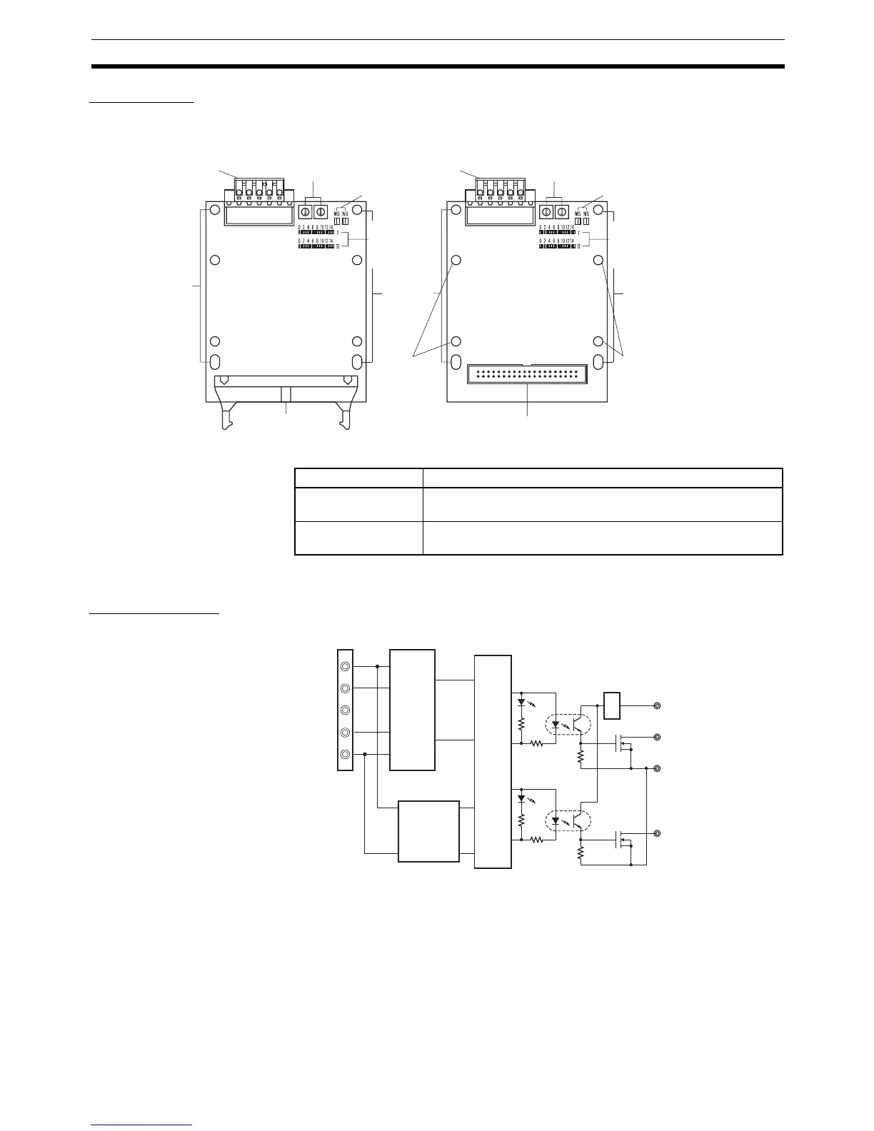
Components
Output Indicators
Note “m” is the first word allocated to the Remote I/O Terminal.
Internal Circuits
DRT2-OD32B and DRT2-OD32BV (NPN)
DeviceNet
communications
connector
Node address
switches
(×10)
DeviceNet
operation
indicators
I/O
operation
indicators
Board
mounting
holes
Board
mounting
holes
I/O connector (MIL) I/O connector
DeviceNet
operation
indicators
Node address
switches
(×10)
DeviceNet
communications
connector
I/O
operation
indicators
Board
mounting
holes
User
customized
board
mounting
holes
User
customized
board
mounting
holes
(×1) (×1)
DRT2-OD32B (NPN)/DRT2-OD32B-1 (PNP) DRT2-OD32BV (NPN)/DRT2-OD32BV-1 (PNP)
Name Meaning
I0 to I15 Indicate the status of bits (contacts) 0 to 15 in word m. Lit
when output is ON; not lit when output is OFF.
II0 to II15 Indicate the status of bits (contacts) 0 to 15 in word m+1. Lit
when output is ON; not lit when output is OFF.
Output
Output
V
G
V+
CAN_H
DRAIN
CAN_L
V−
Internal
circuitry
Photo-
coupler
Photo-
cou

 Loading...


