219
Screw-less Clamp Terminals Section 5-7
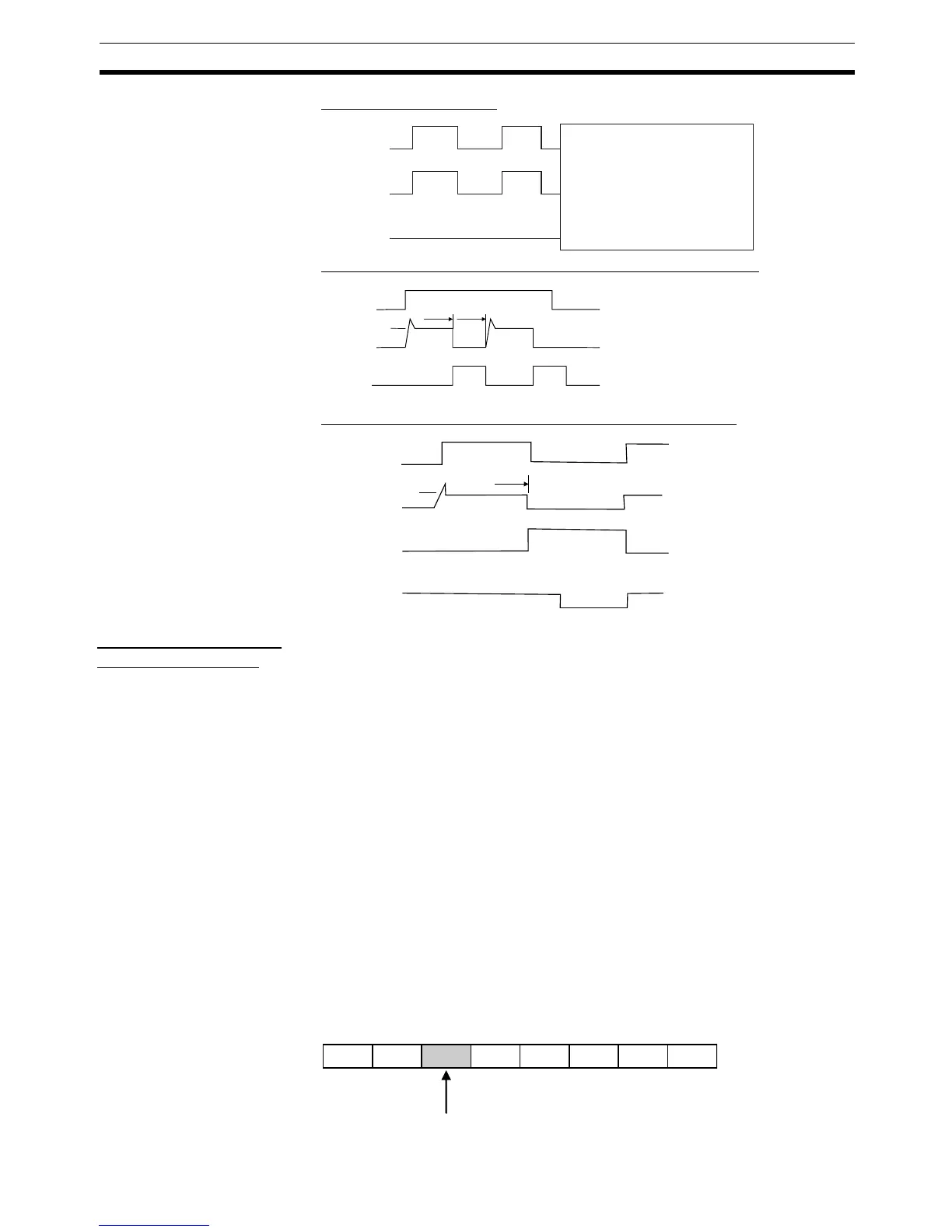
Fig. 1 Normal Operation
Fig. 2 Overload or Short-circuit (Automatic Recovery Mode)
Fig. 3 Overload or Short-circuit (Manual Recovery Mode)
Automatic Recovery
Mode Restrictions
The Unit has load short-circuit protection, but automatic recovery mode is
designed to protect the internal circuits specifically from a brief load short-cir-
cuit.
In automatic recovery mode, the Unit's load short-circuit protection is auto-
matically cleared when Tj = Tr, as shown in Fig. 2. Therefore, as long as the
cause of the short-circuit is not removed, the output's ON/OFF operation will
repeat.
If the Unit is left with a short circuit, the internal temperature will rise, causing
damage to the Unit. Always remove the cause of an external load short-circuit
promptly.
Note When an external load short-circuit is detected, the External Load Shorted
Flag will turn ON in the Unit's Status Area and the indicator corresponding to
the shorted output contact will turn ON. An OR for all contact status will output
to the Short-circuited Flag.
When the Load Shorted Flag turns ON, either hold the status of the bit in the
user program and program to turn OFF all the Unit's outputs, or use an
Explicit message to read the contact that is shorted and turn it OFF. The
Short-circuited Flag is allocated in the fifth bit in the Unit's status information
area.
OUT
ON
OFF
Iout
ON
OFF
LED
ON
OFF
OUT: Output contact
IOUT: Output current
ERR: Alarm output, ERR indicator
Ilim: Current limit
Tj: Transistor junction temperature
Tstd: Thermal shutdown temperature
Tr: Reset temperature
Status
OUT
ON
OFF
I
OUT
ON
OFF
ERR
ON
OFF
I
lim
Tj =Tstd Tj =Tr
OUT
ON
OFF
Iout
ON
OFF
LED
ON
OFF
I lim
Tj =Tstd
ON
OFF
Status
I/O power
supply
76543210
Short-circuited Flag

 Loading...


