246
Advanced Environment-resistive Terminals Section 6-4
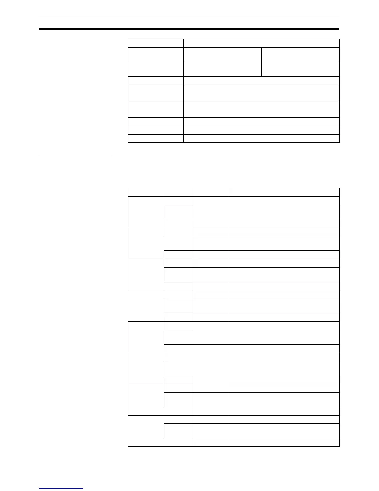
I/O Status Indicators The I/O status indicator displays and their meanings are shown in the follow-
ing table. Refer to the section following on names of components and func-
tions for details on the location of the I/O status indicators. In the indicator
name “1-A,” the “1” indicates the connector number, and the “A” indicates that
it is an I/O status indicator.
ON voltage 9 V DC min. (between each
input terminal and V)
9 V DC min. (between each
input terminal and G)
OFF voltage 5 V DC max. (between each
input terminal and V)
5 V DC max. (between each
input terminal and G)
OFF current 1 mA max.
Input current 3 mA min./point (at 11 V DC)
11 mA max./point (at 24 V DC)
Sensor power supply
voltage
Maximum communications power supply voltage: +0 V
Minimum communications power supply voltage: −1.5 V
ON delay time 1.5 ms max.
OFF delay time 1.5 ms max.
Number of circuits 8 points with one common
Item Specifications
Indicator Color Status Meaning
1-A Yellow ON Input 0 is ON.
Red ON The sensor power of connector 1 has
shorted.
Red Flashing The sensor of connector 1 is disconnected.
2-A Yellow ON Input 1 is ON.
Red ON The sensor power of connector 2 has
shorted.
Red Flashing The sensor of connector 2 is disconnected.
3-A Yellow ON Input 2 is ON.
Red ON The sensor power of connector 3 has
shorted.
Red Flashing The sensor of connector 3 is disconnected.
4-A Yellow ON Input 3 is ON.
Red ON The sensor power of connector 4 has
shorted.
Red Flashing The sensor of connector 4 is disconnected.
5-A Yellow ON Input 4 is ON.
Red ON The sensor power of connector 5 has
shorted.
Red Flashing The sensor of connector 5 is disconnected.
6-A Yellow ON Input 5 is ON.
Red ON The sensor power of connector 6 has
shorted.
Red Flashing The sensor of connector 6 is disconnected.
7-A Yellow ON Input 6 is ON.
Red ON The sensor power of connector 7 has
shorted.
Red Flashing The sensor of connector 7 is disconnected.
8-A Yellow ON Input 7 is ON.
Red ON The sensor power of connector 8 has
shorted.
Red Flashing The sensor of connector 8 is disconnected.

 Loading...


