249
Advanced Environment-resistive Terminals Section 6-4
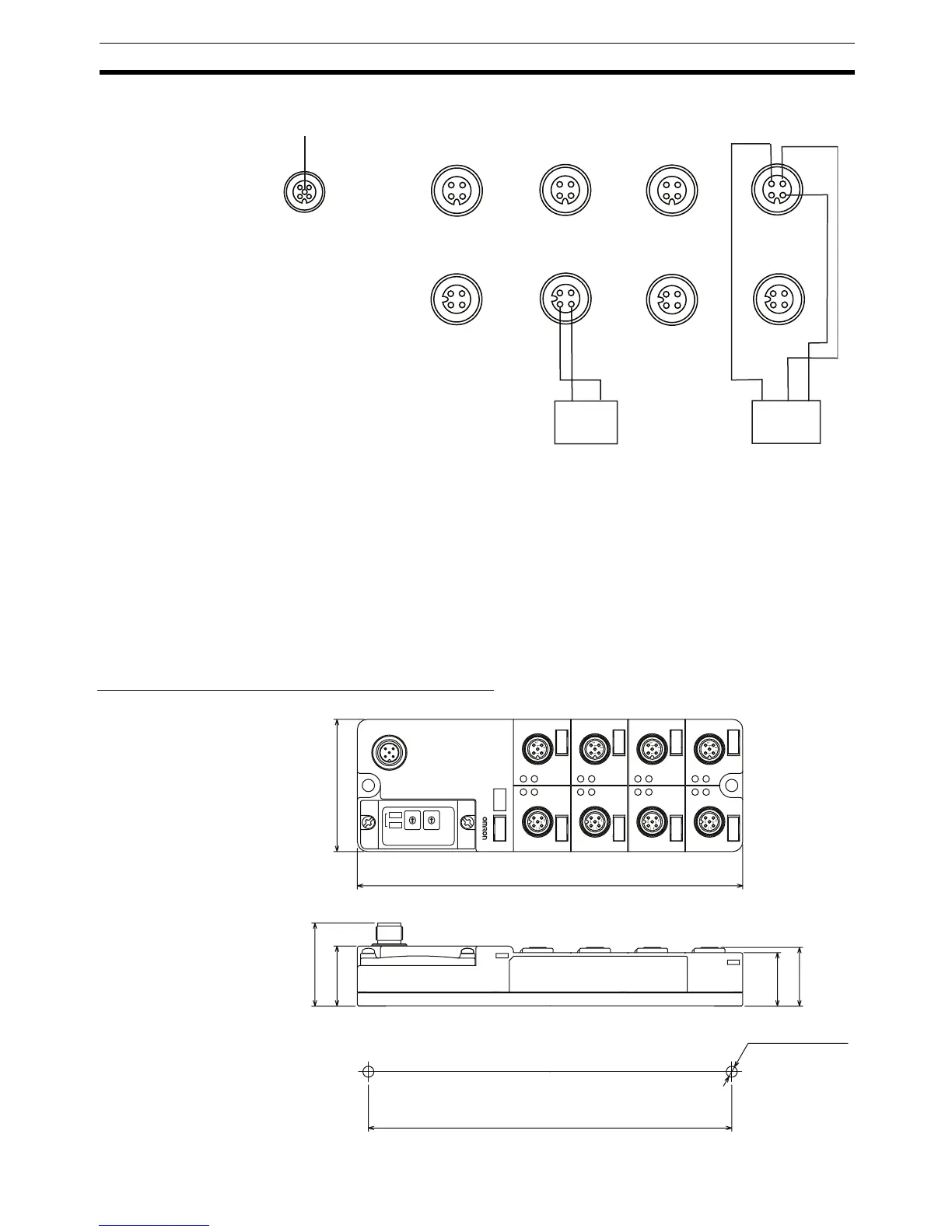
DRT2-ID08C-1 (PNP)
Note 1. Wire colors in parentheses are the previous JIS colors for photoelectric
and proximity sensors.
2. The minimum sensor power supply voltage is a communications power
supply voltage of -1.5 V. Confirm the rated power supply voltage of the con-
nected sensors when selecting the power supply. Refer to Appendix E Cur-
rent Consumption Summary before setting the communications power
supply voltage.
Dimensions: DRT2-ID08C and DRT2-ID08C-1
1
2
4
3
V
NC
G
1
2
4
3
V
NC
G
1
2
4
3
V
NC
G
1
2
4
3
V
NC
G
23
1
4
NC
V
G
23
1
4
NC
V
G
23
1
4
NC
V
G
23
1
4
NC
V
G
1
2
4
V+
CAN H
CAN L
3
5
V−
DRAIN
Input 0 Input 2 Input
4
Input
6
Input 1 Input 3 Input 5
Input 7
Blue (black)
Brown (red)
Blue (black)
Brown (white)
Black (white)
2-wire sensor
(limit switch)
3-wire sensor with
PNP output
(photoelectric or
proximity sensor)
4
IN
87
B
A
B
A
B
A
B
A
B
A
B
A
B
A
A
B
3
2
6
1
5
165±0.2
60
175
37.7
27.3
26.6
24.3
5
4
3
2
1
0
9
8
7
6
5
4
3
2
1
0
9
8
7
6
NOD
ADR
X 10
X 1
Two 5.3 dia. or M5
mounting holes
Mounting hole dimensions

 Loading...


