251
Advanced Environment-resistive Terminals Section 6-4
Note Although the connectors are numbered from 1 to 8, the input bits are num-
bered from 0 to 7. (The input bits are also numbered from 0 to 7 in the Config-
urator display.)
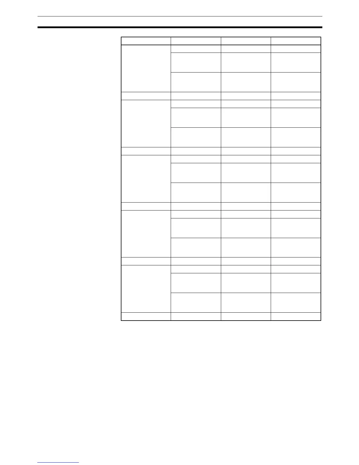
4-A Yellow ON Input 6 is ON.
Red ON The sensor power
of connector 4 has
shorted.
Red Flashing The sensor of con-
nector 4 is discon-
nected.
4-B Yellow ON Input 7 is ON.
5-A Yellow ON Input 8 is ON.
Red ON The sensor power
of connector 5 has
shorted.
Red Flashing The sensor of con-
nector 5 is discon-
nected.
5-B Yellow ON Input 9 is ON.
6-A Yellow ON Input 10 is ON.
Red ON The sensor power
of connector 6 has
shorted.
Red Flashing The sensor of con-
nector 6 is discon-
nected.
6-B Yellow ON Input 11 is ON.
7-A Yellow ON Input 12 is ON.
Red ON The sensor power
of connector 7 has
shorted.
Red Flashing The sensor of con-
nector 7 is discon-
nected.
7-B Yellow ON Input 13 is ON.
8-A Yellow ON Input 14 is ON.
Red ON The sensor power
of connector 8 has
shorted.
Red Flashing The sensor of con-
nector 8 is discon-
nected.
8-B Yellow ON Input 15 is ON.
Indicator Color Status Meaning

 Loading...


