262
Standard Environment-resistive Terminals Section 6-5
Note 1. The I/O status indicator “B” is not used by Units with 4 inputs.
2. Although the connectors are numbered from 1 to 4, the input bits are num-
bered from 0 to 3. (The input bits are also numbered from 0 to 7 in the Con-
figurator display.)
I/O Power Supply Indicator
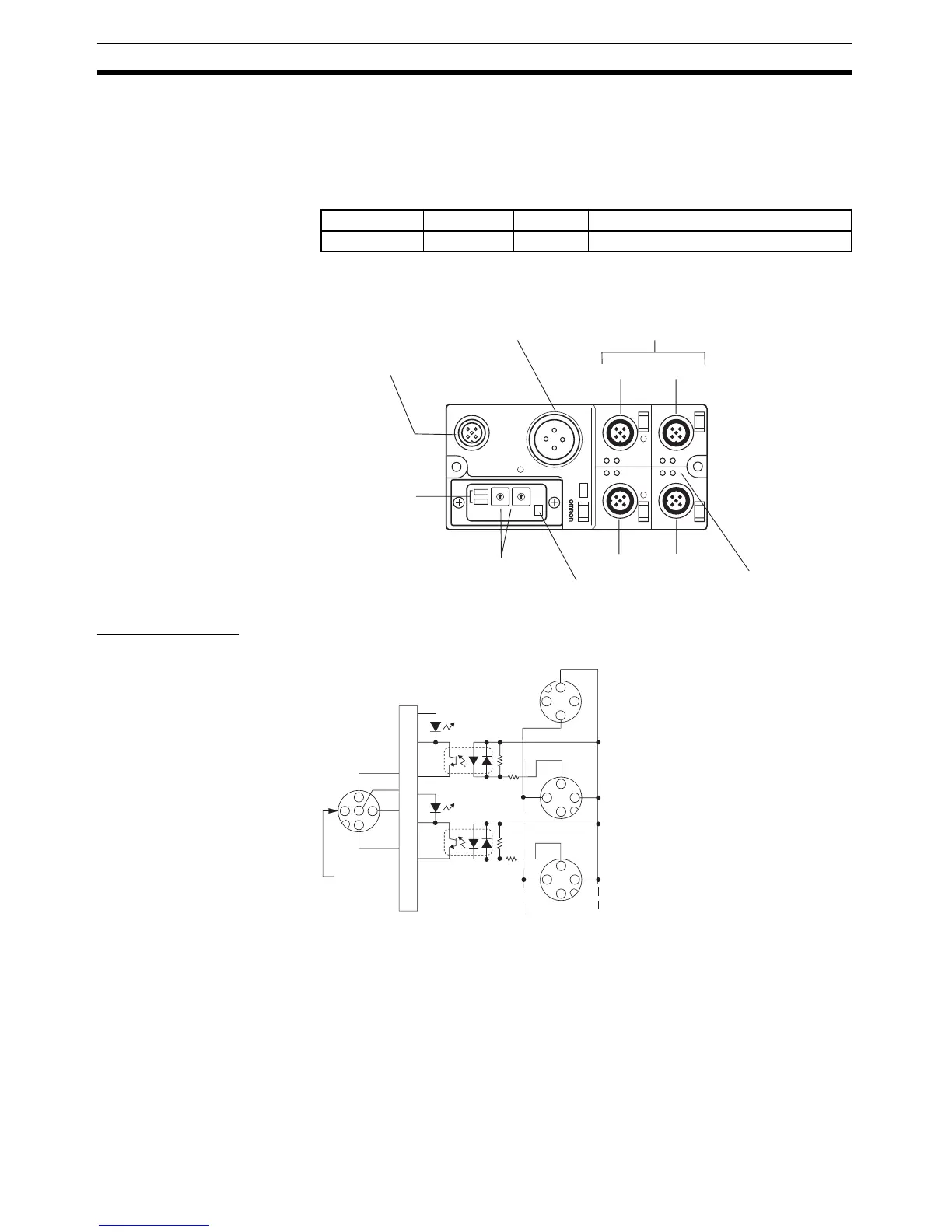
Component Names and Functions: DRT2-ID04CL and DRT2-ID04CL-1
Internal Circuits
DRT2-ID04CL (NPN)
Indicator Color Status Meaning
AUX PWR Green ON I/O power is being supplied.
I/O power supply status indicator
I/O status indicators
Connector 2
Connector 4
Input connectors
DeviceNet indicators
Top: MS indicator
Bottom: NS indicator
Connector 1
Connector 3
External power supply
connector
DeviceNet communications
connector
Rotary switches
Used to set node addresses.
5
4
3
2
1
0
9
8
7
6
5
4
3
2
1
0
9
8
7
6
A
1
B
2
A
B
A
3
B
4
A
B
IN
NOD
ADR
X 10
X 1
AUX
PWR
CAN-L
CAN-H
V+
V−
DRAIN
V
4
5
2
1
3
G
IN0
IN1
V
G
V
G
3
1
4
2
4
2
3
1
4
2
3
1
Internal circuits

 Loading...


