279
Standard Environment-resistive Terminals Section 6-5
name “1-A,” the “1” indicates the connector number, and the “A” indicates that
it is an I/O status indicator.
Note Although the connectors are numbered from 1 to 8, the input bits are num-
bered from 0 to 7.
I/O Power Supply Status
Indicator
Component Names and Functions: DRT2-WD16CL and DRT2-WD16CL-1
Indicator Color Status Meaning
1-A Yellow ON Output 0 is ON.
1-B Yellow ON Output 1 is ON.
2-A Yellow ON Output 2 is ON.
2-B Yellow ON Output 3 is ON.
3-A Yellow ON Output 4 is ON.
3-B Yellow ON Output 5 is ON.
4-A Yellow ON Output 6 is ON.
4-B Yellow ON Output 7 is ON.
5-A Yellow ON Output 8 is ON.
5-B Yellow ON Output 9 is ON.
6-A Yellow ON Output 10 is ON.
6-B Yellow ON Output 11 is ON.
7-A Yellow ON Output 12 is ON.
7-B Yellow ON Output 13 is ON.
8-A Yellow ON Output 14 is ON.
8-B Yellow ON Output 15 is ON.
Indicator Color Status Meaning
AUX PWR Green ON I/O power is being supplied.
5
4
3
2
1
0
9
8
7
6
1
B
2
A
B
34
56
A
7
B
8
A
B
IN
NOD
ADR
X 10
X 1
AUX
PWR
5
4
3
2
1
0
9
8
7
6
A
B
A
B
A
B
A
B
A
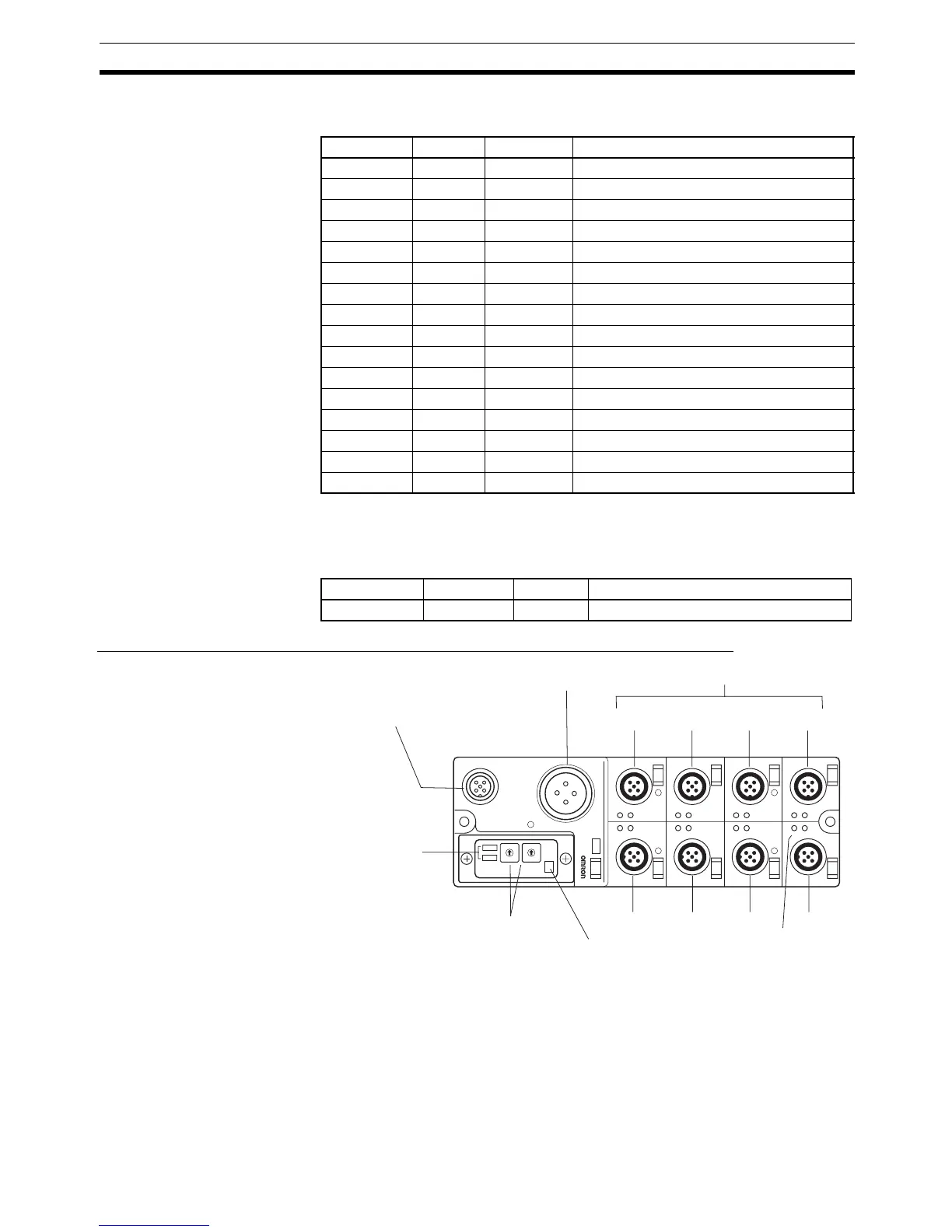
I/O power supply
status indicator
I/O status indicators
Connector 2
Connector 4
Output connectors
DeviceNet indicators
Top: MS indicator
Bottom: NS indicator
Connector 1
Connector 3
External power supply
connector
DeviceNet communications
connector
Rotary switches
Used to set node addresses.
Connector 6
Connector 8
Connector 5
Connector 7

 Loading...


