289
Mounting and Wiring Environment-resistive Slaves Section 6-6
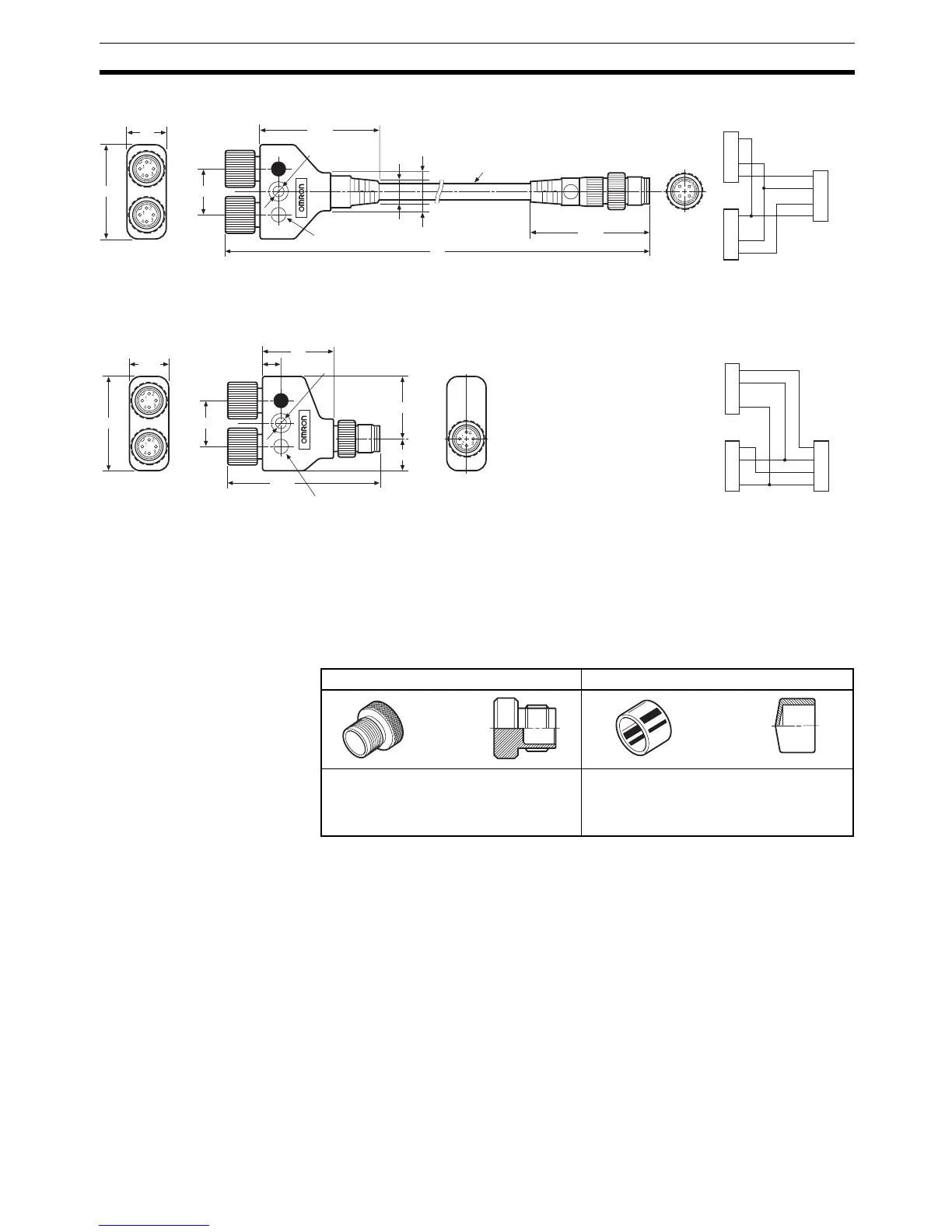
XS2R-D426-@11-F Y-joint with Plug/Socket (Connector on Both Ends)
Note Refer to the Sensor I/O Connector Group Catalog (Cat. No. X073) for details.
XS2R-D426-1 Y-joint with Plug/Socket (without Cable)
Note Tighten the connector by hand to a torque of 0.39 to 0.49 N·m. If the connec-
tor is not tightened sufficiently, it will not provide the expected degree of pro-
tection and may become loose due to vibration. Do not use pliers or other
tools to tighten the connectors, because these tools may damage the connec-
tors.
Always cap unused connectors with an XS2Z-12 Waterproof Cover or XS2Z-
15 Dust Cover shown in the following diagram.
Maintaining Enclosure Ratings
Note 1. The IP67 enclosure rating will not be met if the surfaces where the contact
block and cover meet are subjected to excessive force. Protect the contact
block and cover from excessive force.
The IP67 standard is lower than waterproof standards. Do not submerge
the system components.
The body of the components is plastic resin. Do not place objects on the
components or allow the components to be stepped on.
2. There are two kinds of wiring for OMRON Two-wire Proximity Sensors
(pre-wired with connector). One switch has IEC pin arrangement (M1GJ
type) and the other has OMRON pin arrangement (M1J type). Refer to the
XS2Z-12 Waterproof Cover XS2Z-15 Dust Cover
The connector will meet IP67 standards
if a Waterproof Cover is attached.
Always tighten the connector by hand to
a torque of 0.39 to 0.49 N·m.
Press the Dust Cover onto the connector
firmly. The Dust Cover will protect the con-
nector from dust, but does not meet IP67
standards.
4
CN2
3
2
1
4
CN1
3
2
1
1
2
3
4
CN2
CN1
18
45.5
L
8.5
13.6
35
15
44.7
6 dia.
4.6 dia.
Blue mark
Wiring diagram
1
CN2
2
3
4
1
CN1
2
3
4
1
CN0
2
3
4
7
CN2
CN1
CN0
18
24.5
12.5
27
58.3
(37)
15
4.5 dia.
Blue mark
Wiring diagram

 Loading...


